8 System installation instructions 0020292325_01
Work step Selected information/measures
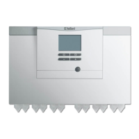
9 Heat pump control module
► Connecting the heat pump control module
► Establishing the power supply
► Install the heat pump control module.
► Route the cables through the strain reliefs from below and into the product.
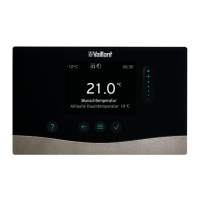
10 Outdoor temperature sensor
► Connecting the outdoor temperature sensor
► Observe the installation conditions (wind-protected, no direct sunlight, no
effect from heat sources, etc.)
→ sensoCOMFORT operating and installation instructions
11 Bus coupler
► Connecting the bus coupler
12 Outdoor unit
► Connecting the outdoor unit
► Select a correct cable cross-section.
► Comply with the connection conditions for the energy supply company.
► Determine whether an electrical connection 1~/230 V or 3~/400 V (→ data
plate) is required.
► Determine whether the power supply should be set up using a single-tariff
meter or a dual-tariff meter.
Condition: Depending on the installation site
► Install one or two type-B residual-current circuit breakers for the outdoor unit,
depending on the connection type.
13 Outdoor unit
► Connecting a limit thermostat
► Observe the wiring diagram.
→ aroTHERM plus installation and maintenance instructions, appendix C
14 Electrical house installation
► Installing components for the energy supply
company lockout function
Condition: Power supply via a dual-tariff meter
Actuating the ESCO contact
15 Heat pump control module
► Connecting the system temperature sensor
► Connecting the contact for the energy supply
company lockout on the heat pump control
module
► Observe the wiring diagram.
→ VWZ AI installation instructions, appendix B
16 Outdoor unit, heat pump control module,
system control, communication unit, bus
coupler
► Installing the eBUS line
► Earthing connection pipes
► Check whether the existing conductor cross-sections for the eBUS line are
sufficient for the planned line length.
Validity: Indoor unit
► Do not connect more than two eBUS lines to the plug on the control PCB.
Condition: Metallic connection pipes
► Earth the connection pipes.
3.5 Completing installation
→ aroTHERM plus installation and maintenance instructions, from section 7.13 onwards
Work step Selected information/measures
17 Building
► Sealing the wall duct
► Seal the wall duct using a suitable sealing compound.
3.6 Starting up the system
→ aroTHERM plus installation and maintenance instructions, from section 8.1 onwards
→ VWZ AI installation and maintenance instructions, from section 7.1 onwards
Work step Selected information/measures
1 Heating circuit
► Filling and purging the heating installation
► Observe the requirements for the heating/filling and supplementary water.
► Use the purge programme. Ensure that the purging valves on the heating
manifold are open.
2 Outdoor unit
► Switching on the power supply
3 Heat pump control module
► Switching on the power supply

 Loading...