0020292325_01 System installation instructions 7
3.2 Preparing for installation
→ aroTHERM plus installation and maintenance instructions, from section 4.1 onwards
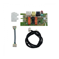
→ VWZ AI installation instructions, from section 4.1 onwards
→ Installation instructions for the heat recovery module
→ Accessory set-up instructions
Work step Selected information/measures
1 Building
► Establishing a wall duct
2 Outdoor unit installation site, heat pump
control module
► Defining the installation site
► Comply with the specific conditions for the installation site and the installation
type.
Important planning dimensions:
– Maximum height difference between the outdoor unit and the heat recovery
module: 15 m
– Remaining feed head of the heat source circuit pump:
→ aroTHERM plus installation and maintenance instructions, from sec-
tion 5.4 onwards
– Minimum clearances and installation clearances:
→ aroTHERM plus installation and maintenance instructions, from sec-
tion 5.4 onwards
→ Installation and maintenance instructions for the heat pump control
module
3 Outdoor unit
Condition: Depending on the installation
type/condition
► Establishing the strip foundations
► Mounting the unit mounting bracket
► Procuring and installing other accessories
► Setting up/installing the product
► If required, use the transport belts that are supplied.
Condition: Establishing the strip foundations
► Ensure that the condensate discharge can be positioned in the centre above
the downpipe.
4 Outdoor unit
► Installing the condensate discharge pipe
► Ensure that condensate does not reach paths (ice formation).
5 Heat pump control module
► Mounting the product
3.3 Installing the heating and domestic hot water circuit
→ aroTHERM plus installation and maintenance instructions, from section 6.1 onwards
→ Installation instructions for the heat recovery module
→ Accessory set-up instructions
Work step Selected information/measures
6 Heating circuit
► Connecting the heat recovery module
► Installing heating circuit connections
► Connecting the bypass valve
► Connecting the expansion vessel
► Observe the connection symbols.
► Adjust the bypass valve in such a way that the minimum volume flow.
► Note the remaining feed head of the heat pump and the pressure losses in
the system.
7 Safety devices
► Installing the safety devices
► Ensure that all of the required safety device have been installed in the sys-
tem.
3.4 Installing the electrical connections
→ aroTHERM plus installation and maintenance instructions, from section 7.1 onwards
→ ecoTEC VCW installation and maintenance instructions, from section 6.1 onwards
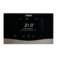
→ sensoCOMFORT operating and installation instructions, from section 3 onwards
→ VWZ AI installation instructions, from section 5.1 onwards
→ Accessory set-up instructions
Work step Selected information/measures
8 System control
► Connecting the system control
► Ideally, install the system control in a living room.
 Loading...

