5 Installation
16 Installation instructions Heat pump control interface module 0020291573_00
4.4 Installing the product
PE N L
230 V~
+ -
Bus VF1 SP1
PE N L
230 V~
AF DCF
DCF/AF ME EVU
PE N L
MA1
PE N L
MA2
PE N
Auf
Zu
UV1
PE N 1 2
ZH
2 1 2 1
2 1
2 1
1
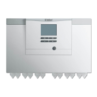
1. Mount the product and the supplied installation access-
ory on the wall. Use the fixing points (1) for this.
2. Connect the product. (→ Page 17)
4.5 Closing the casing
1. Insert the casing cover at the top into the hinges.
2. Fold down the casing cover.
3. Tighten the bolt on the underside of the casing.
5 Installation
5.1 Installing the VR 10 standard sensor
Note
You can use the VR 10 as a cylinder temperature
sensor (for example, as an immersion sensor
in a cylinder dry pocket), as a flow temperature
sensor (for example, in the low loss header) or as
a surface-mounted sensor. We recommend that
the pipe with the sensor be insulated to ensure
optimum temperature recording.
▶ If you use the VR 10 as a surface-mounted sensor, se-
cure the VR 10 to a return/flow pipe using the enclosed
strap.
5.2 Installing the external temperature sensor
Installing the outdoor temperature sensor
1 Connection cable to
the VRC 693 external
temperature sensor
2 Connector in the
product
▶ Install the outdoor temperature sensor in accordance with
its enclosed set-up instructions.
5.3 Preparing the electrical installation
Danger!
Risk of death from electric shock as a res-
ult of an improper electrical connection!
An improper electrical connection may neg-
atively affect the operational safety of the
product and result in material damage or per-
sonal injury.
▶ Only carry out the electrical installation if
you are a trained competent person and
are qualified for this work.
1. Observe the technical connection conditions for con-
necting to the energy supply company's low-voltage
network.
2. If the local power supply network operator requires that
the heat pump is controlled using an ESCO blocking
signal, install a corresponding contact switch as pre-
scribed by the power supply network operator.
3. Determine whether the power supply for the product
should be set up with a single-tariff meter or a dual-tariff
meter.
4. Connect the product via a fixed connection and a parti-
tion with a contact gap of at least 3 mm.
5. Leave the cable cross-section for the connection cable
to the distribution box unchanged.
6. If the power supply cable for this product is damaged, it
must be replaced by the manufacturer or their customer
service or a similarly qualified person in order to prevent
any hazards.
7. Ensure that the nominal voltage of the power grid cor-
responds to that of the product's main power supply
cabling.
8. Make sure that access to the power supply is always
available and is not covered or blocked.

 Loading...