Appendix
22 Installation instructions Heat pump control interface module 0020291573_00
Appendix
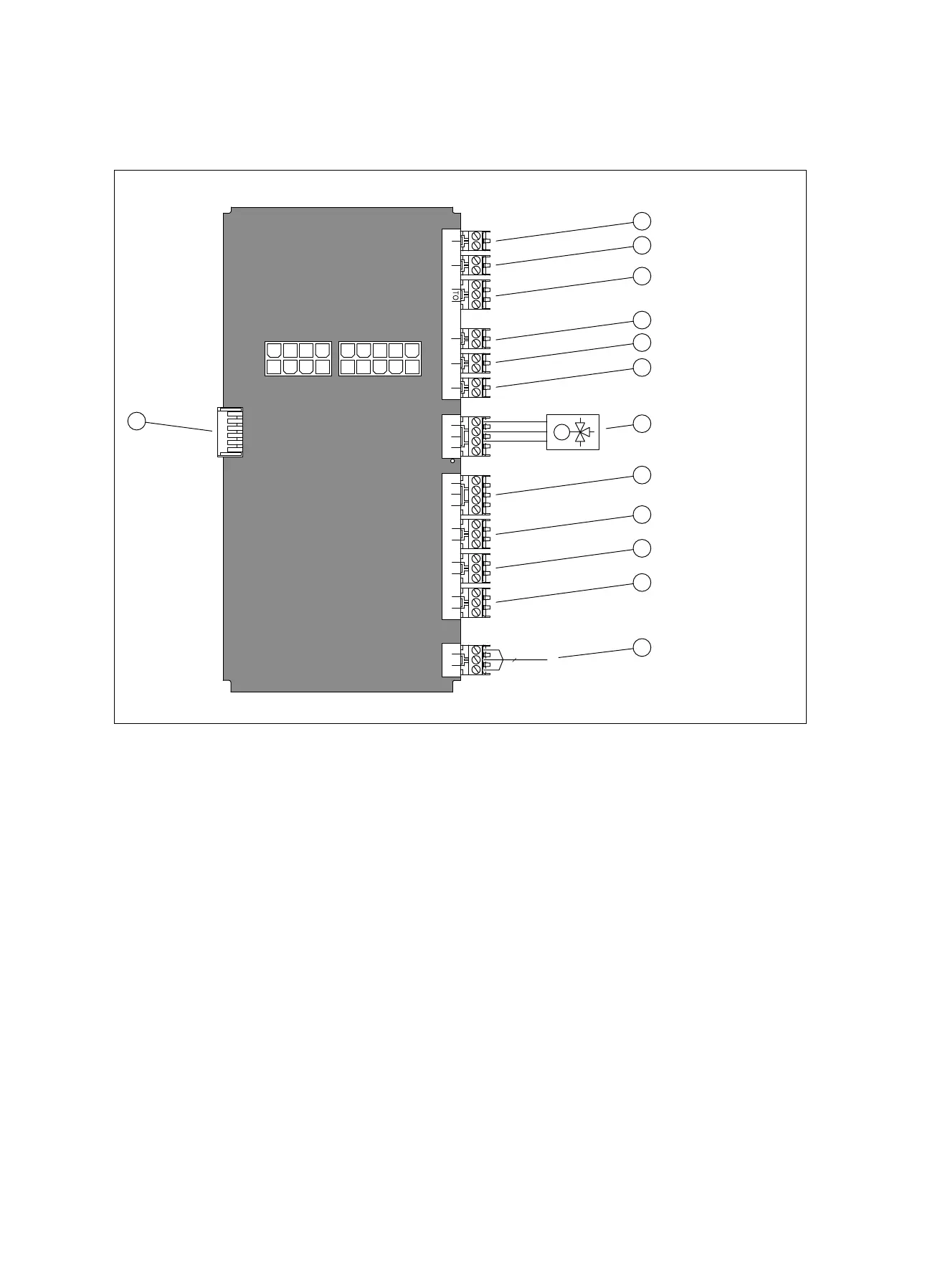
A Printed circuit board
PE N L
3
230 V~
X4 X5 X6 X7 X8
X3
X1
X51
+ -
Bus VF1 SP1
PE N L
230 V~
AF DCF
DCF/AF ME EVU
PE N L
MA1
PE N L
MA2
PE N
Auf
Zu
UV1
PE N 1 2
ZH
2 1 2 1
2 1
2 1
M
1
2
3
4
5
6
7
8
9
10
11
12
13
1 [ESCO] Energy supply company contact
2 [MI] Multi-function input: Manual circulation switch-on
3 [DCF/AF] DCF/outdoor temperature sensor
4 [SP1] Domestic hot water cylinder temperature
sensor
5 [VF1] System temperature sensor
6 [BUS] eBUS bus connection (outdoor unit, system
control)
7 [X8] ZH external back-up heater or MEH 60
8 [X7] UV1 external prioritising diverter valve
9 [X6] MA2 multi-function output 2: Circulation pump,
anti-legionella pump, zone valve, dehumidifying unit
10 [X5] MA1 multi-function output 1: Zone valve (basic
system diagram 8), cooling signal (basic system
diagrams 8, 9, 12), intermediate heat exchanger
pump (basic system diagrams 10, 11, 13, 16)
11 [X4] 230 V power supply for optional accessories
12 230 V power supply
13 [X51] Display edge connector

 Loading...