Installation 5
0020291573_00 Heat pump control interface module Installation instructions 17
5.3.1 Carrying out the wiring
1. Ensure that the mains voltage is correctly disconnected
from the safety extra-low voltage.
2. Only connect power supply cables to the terminals that
are marked for the purpose.
3. Shorten the connection cables according to require-
ments.
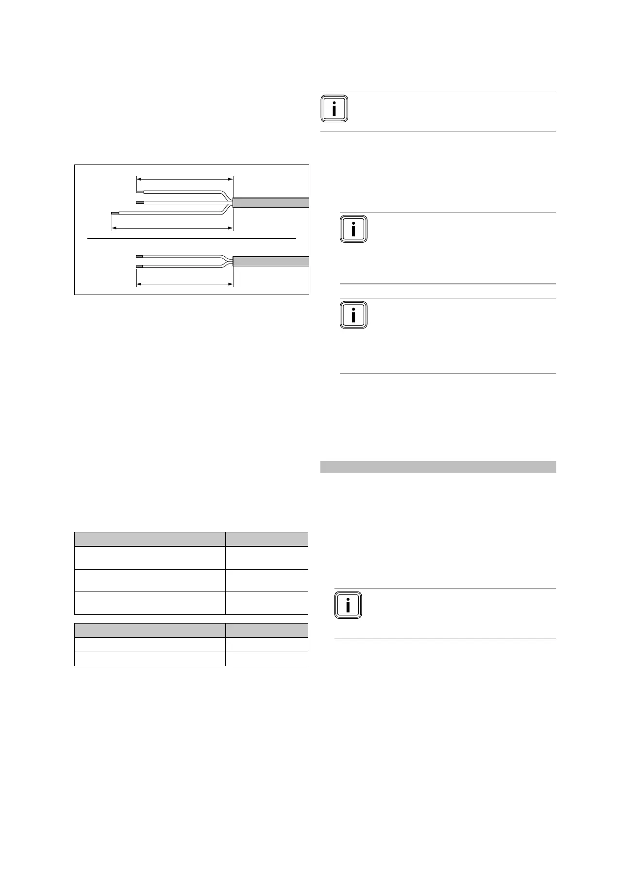
4. Strip the electrical wire as shown in the figure. In doing
so, ensure that the insulation on the individual conduct-
ors is not damaged.
5. Ensure the inner conductor insulation is not damaged
when stripping the outer sheathing.
6. Only strip inner conductors just enough to establish
good, sound connections.
7. Fit conductor end sleeves on the stripped ends of the
conductors.
8. Screw the respective plug to the connection cable.
9. Check whether all conductors are inserted mechanic-
ally securely in the plug terminals. Remedy this if ne-
cessary.
10. Plug the plug into the associated PCB slot.
5.3.2 Requirements for lines
▶ Use standard commercial lines for the wiring.
▶ Use sheathed cables for 230 V lines (e.g. NYM 3 x 1.5).
▶ Do not use flexible lines for 230 V lines.
Type of line Min. cross-section
Cross-section of 230 V connection cable
(pump or mixer connection cable)
≥ 1.5 mm²
Cross-section of eBUS line (extra low
voltage)
≥ 0.75 mm²
Cross-section of sensor line (extra low
voltage)
≥ 0.75 mm²
Type of line Max. length
Sensor lines ≤ 50 m
Bus lines ≤ 300 m
5.3.3 Requirements for the quality of the mains
voltage
For the mains voltage of the single-phase 230 V network, a
tolerance of +10% to -15% must be provided.
5.3.4 Connecting the product
Note
The power supply cable and the eBUS line are not
included in the scope of delivery.
1. Connect the product using a fixed connection and a
partition with a contact gap of at least 3 mm (e.g. fuses
or power switches).
2. Wire the product in accordance with the wiring diagram;
see appendix.
Note
If the diverter valve should be in the position
for cylinder charging, 230 V is output to the
"Open" contact. If the diverter valve should
not be in the position for cylinder charging,
230 V is output to the "Closed" contact.
Note
The ESCO contact is used to connect a
blocking signal (can be configured on the
control).
Contact open: Operation permitted
Contact closed: Operation blocked
3. Secure all lines in the product using the enclosed strain
reliefs.
4. Close the casing. (→ Page 16)
5.4 Installing components for the energy supply
company lockout function
Condition: Energy supply company lockout function provided
The heat generation from the heat pump can be switched off
temporarily by the energy supply company – usually by using
a ripple control receiver.
The signal for the shutdown is fed to connection ESCO for
the heat pump control module.
▶ Install and wire additional components in the building's
meter/fuse box. To do this, follow the wiring diagram in
the appendix.
Note
In the event of control via connection ESCO,
the energy supply does not have to be discon-
nected on-site.
▶ Connect a 2-pole control cable to the relay contact (po-
tential-free) for the ripple control receiver and to connec-
tion ESCO.
▶ In the system control, set whether the electric back-up
heater, the compressor or both should be blocked via
ESCO.

 Loading...