Do you have a question about the Vaisala DMP Series and is the answer not in the manual?
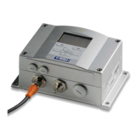
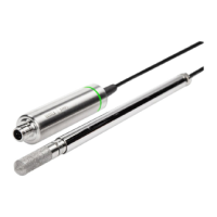
The Vaisala DMP Series User Guide describes a range of Vaisala Indigo-compatible dew point and temperature probes (DMP5, DMP6, DMP7, and DMP8) designed for demanding dew point measurement applications. These probes are two-part structures, with measurement electronics contained in the probe body and sensor(s) in the probe head. The probe body and the probe head are connected by a fixed cable, with length options depending on the probe model. The probes are compatible with Vaisala Indigo transmitters and the Vaisala Indigo80 Handheld Indicator, and can be connected to Vaisala Insight PC software for configuration, calibration, diagnostics, and temporary online monitoring.
The DMP series probes utilize Vaisala DRYCAP® dew point measurement technology, which ensures accurate measurement with excellent long-term stability. This technology is based on two innovations: the proven capacitive thin-film polymer sensor and the self-diagnostic functions that the software performs automatically as needed. The sensor's thin-film polymer absorbs or releases water vapor as the surrounding humidity increases or decreases, changing the dielectric properties of the polymer and thus the capacitance, which is converted into a humidity reading. The capacitive polymer sensor is bonded together with a temperature sensor, and dew point is calculated from the humidity and temperature readings.
The automatic sensor functions include autocalibration, sensor purge, and sensor warming. These are key elements in achieving stability, rapid response time, and condensation resistance of the DRYCAP® sensors.
Autocalibration Autocalibration optimizes the sensor for measurement stability in dry environments. It warms the sensor for a short period, and the dew point and drift are then corrected to correspond to the calibrated values. During autocalibration, all available output parameters are locked. DMP series probes perform autocalibration at 1-hour intervals, and whenever sensor purge is performed.
Sensor Purge Sensor purge is an automatic procedure that minimizes drift at wet end readings. The sensor is heated to a high temperature, evaporating excess molecules out of the sensor polymer. This, together with autocalibration, results in a very small drift of the sensor due to the very linear behavior of the polymer technology. DMP probes perform sensor purge when powered on (known as startup purge) and at one-day intervals (known as internal purge).
Condensation Prevention Functions The sensor warming feature of the condensation prevention function improves the condensation tolerance of the probe. It warms the humidity sensor when necessary to keep the sensor temperature above the dew point of the measurement environment. When sensor warming is activated, all temperature-dependent output parameters become unavailable. The temperature compensation setting is set to read the temperature from an external source. The output parameters become available again 4 minutes after the warming is stopped. The humidity limit where sensor warming activates is 80 %RH for DMP probes with 5 sensors and 70 %RH for DMP probes with 8 sensors.
Environmental Compensation Environmental compensations improve the measurement accuracy of the probe. This can be configured with the Insight software or the Indigo80 handheld indicator, or using the Modbus protocol.
Filtering Factor The filtering factor determines how quickly the results of measurement cycles are reflected in values of output parameters. A higher filtering factor slows down the response time of the measurement. Filtering out rapid changes and measurement noise.
The DMP series probes offer a comprehensive list of output parameters, superior chemical resistance, condensation prevention, traceable calibration certificates, standalone Modbus® RTU over RS-485, and compatibility with Indigo transmitters and the Indigo80 handheld indicator.
DMP5 Specifications:
DMP6 Specifications:
DMP7 Specifications:
DMP8 Specifications:
Installation: The installation location for the probe should verify the operating environment specification of the probe model. The probe head typically has a much wider operating temperature range than the probe body. If the temperature of the measured environment differs greatly from ambient temperature, the entire probe head and preferably plenty of cable must be inside the measured environment to prevent measurement inaccuracy caused by heat conduction along the cable. Probe mounting options are model-specific.
Connecting to Indigo Transmitters: DMP series probes are Indigo-compatible. Indigo transmitters offer additional options for outputs, measurement viewing, status monitoring, and configuration interface access.
Connecting to Indigo80 Handheld Indicator: The Indigo80 Handheld Indicator is a portable diagnostics tool that accommodates up to two Vaisala Indigo-compatible probes or transmitters for measuring a wide range of parameters. It provides real-time measurements, log measurement data, probe calibration information, and allows configuration of probe features and settings such as condensation prevention, compensation setpoints, sensor purge, filtering factor, and serial communication.
Vaisala Insight Software: Vaisala Insight software is a configuration software for Indigo-compatible devices. It allows users to see probe information and status, see real-time measurements, record data, update probe calibration information, and configure probe features.
Cleaning the Probe: The probe, probe body, and cable can be cleaned by wiping them with a soft, lint-free cloth moistened with water or a suitable cleaning agent, such as isopropyl alcohol. Do not wipe the filter; wiping the filter may block its pores and/or deposit residue on the filter. If the filter is heavily contaminated, replace it.
Changing the Probe Filter: Sensors are easily damaged when the filter is not in place. Handle the probe head carefully.
Calibration and Adjustment: Calibration compares the measurement output of the device to a known reference, such as a known environment in a calibration chamber or the output of a reference instrument. Correcting the reading of the device so that it measures accurately is referred to as adjustment. The probe is fully calibrated and adjusted as shipped from the factory. To maintain the accuracy of the measurement, calibrate and adjust the probe as needed. Typical calibration interval is one year, but depending on the application, it may be necessary to check the accuracy more frequently.
Troubleshooting: The manual provides a troubleshooting table for common issues such as measurement output errors, probe status indicator LED being red, and values of measurement parameters stopping changing for a few minutes. It also lists error messages and warnings with recommended actions.
Restoring Factory Default Settings: If needed, users can restore the probe back to its factory default settings using the Insight software or the Indigo80 handheld indicator. This will also clear any user adjustment and restore the latest adjustment performed by Vaisala.
| Brand | Vaisala |
|---|---|
| Model | DMP Series |
| Category | Measuring Instruments |
| Language | English |