2.2 RFL100 Parts
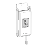
Figure 2 Front and Display
1 Service port connection indicator.
2 Battery level indicator.
3 Currently measured values.
4 Connection indicators.
5 Status LED. Blinks green for normal
operation, red for error or alarm.
6 Signal strength of access point
connection.
7 Alarm indicators. Alarms are
configured in viewLinc Enterprise
Server software.
8 Detachable probe or probe cable.
Figure 3 Under the Silicone Plug
1 Service port (Micro-USB).
2 Refresh button. Push to enable a faster
wireless scanning interval for one hour.
Also wakes up the display if it has
been turned o remotely, and shows
firmware version and currently
connected VaiNet channel.
RFL100 User Guide M211861EN-A
8

 Loading...