List of Figures
Figure 1 Connecting RFL100 to the viewLinc Monitoring System........................ 7
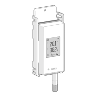
Figure 2 Front and Display............................................................................................... 8
Figure 3 Under the Silicone Plug.................................................................................... 8
Figure 4 Rear and Inside................................................................................................... 9
Figure 5 Mounting Bracket...............................................................................................9
Figure 6 Alarm Indicators on RFL100 Display............................................................ 11
Figure 7 RFL100 with High Alarm Active on Channel 1...........................................12
Figure 8 RFL100 with High-High Alarm Active on Channel 1................................ 12
Figure 9 RFL100 Mounting Methods...........................................................................20
Figure 10 RFL100 Remote Management using viewLinc Enterprise Server...... 24
Figure 11 RFL100 Properties in viewLinc.....................................................................25
Figure 12 RFL100 Data Logger Dimensions with Mounting Bracket................... 49
Figure 13 RFL100 Data Logger Dimensions................................................................50
Figure 14 RFL100 Mounting Bracket Dimensions......................................................50
List of Figures
3

 Loading...