EasyManua.ls Logo

VALCO MELTON D10 User Manual

Default Icon
313 pages
To Next Page IconTo Next Page
Page #1 background imageLoading...
Page #1 background image
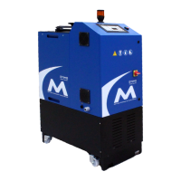
D10/D16 Hot Melt Unit
Manual Number: MM113
Revision Date: 8/2019

Table of Contents

Questions and Answers:

VALCO MELTON D10 Specifications

General IconGeneral
CategoryMelting Machines
Power Consumption1.5 kW
Number of Pumps1
Power Supply230 VAC, 50/60 Hz
Temperature RangeAmbient to 400°F (204°C)
MaterialSteel
Dimensions400 x 300 x 400 mm
Melt Rate2 kg/hour
ModelVALCO MELTON D10

Summary

Section 1 - Introduction

Description

Describes the D10/D16 hot melt unit's features and capabilities.

Nameplate Information

Details the information found on the unit's nameplate.

S Number Configuration

Explains how the S number is used to configure the unit for specific customer needs.

Section 2 - Safety and Use

General Safety Precautions

Covers reading manual, symbols, owner responsibilities, limitations, and installation/operation/shutdown safety.

Handling Adhesive Incidents

Provides procedures for dealing with hot adhesive contact, fume inhalation, and fire/explosion.

Hose Safety Information

Details do's and don'ts for safely handling and installing hot melt hoses.

Section 3 - Basic Features

Key Features

Identifies and illustrates the main components and features of the D-Series Hot Melt Systems.

Section 4 - Installation

Choosing a Location

Provides guidelines for selecting an appropriate and safe location for the hot melt unit.

Connecting the Electrical Power

Details the procedure and safety precautions for connecting the unit to electrical power.

Connecting the Hoses

Explains how to route and connect heated hoses to the unit and applicators.

Input/Output Connections

Describes the CPU board's input/output connection interface and options.

Section 5 - Setup

Control Panel Overview

Identifies and describes the functions of the control panel items and buttons.

Programming Temperatures

Explains how to access and set temperatures for the tank and zones.

Over Temperature Alarm

Details the setting for the over temperature alarm tolerance and its function.

Pressure Setup

Details how to configure pressure monitoring for high or low pressure alarms.

Shift Times/Setback Times

Covers programming of start, end, and setback times for three shifts.

Adjusting the Pressure Control Valve

Details how to adjust the single-stage relief valve for system pressure.

Section 6 - Operation

Start the Unit

Provides step-by-step instructions to power up and start the hot melt unit.

Pump Operation

Covers pump activation, enabling, and status indicators.

Setback

Details how the unit automatically enters setback mode based on programmed times or manual activation.

Filling the Tank

Provides instructions and safety precautions for filling the unit's tank with adhesive.

Section 7 - Maintenance

General Maintenance Procedures

Recommends general maintenance practices for optimal system performance and longevity.

Flushing the System

Explains when and how to flush the system, recommending paraffin wax.

Changing the Filter

Provides instructions on how to unscrew and replace the filter assembly.

Section 8 - Troubleshooting and Repair

Troubleshooting Guide

Provides a table listing common problems, their causes, and possible solutions.

SECTION 9 - SPECIFICATIONS

Unit Specifications

Lists technical specifications including gun attachments, tank capacity, melt rate, pump, viscosity range, etc.

Dimensions - D10

Provides the physical dimensions of the D10 unit.

Dimensions - D16

Provides the physical dimensions of the D16 unit.

Section 10 - Part Number List

How to Order Parts

Provides contact information for ordering parts from Valco offices worldwide.

D10 Unit Part Numbers

Lists part numbers and descriptions for different D10 unit configurations.

D16 Unit Part Numbers

Lists part numbers and descriptions for different D16 unit configurations.

Option Kits

Lists available option kits and their associated instruction sheets.

Pump Kits

Lists various pump kits with part numbers and descriptions.

Section 11 - Warranty

Warranty Information

Outlines the company's warranty policy for its equipment against defects in material and workmanship.

Hot Melt Units, Hoses, Valves, Guns, and Related Equipment Warranty

Details the warranty period for hot melt components, including exceptions for cast-in heaters.

Section 12 - Service

Contacting Technical Support

Provides information on how to contact ValcoMelton Technical Support for assistance with system problems.

Appendix A - Password Levels

Level 2 - Advanced Operator (PIN Code: 1234)

Details the advanced operator level, requiring PIN code 1234, for accessing system setup parameters.

Level 3 - Supervisor (PIN Code: 6550)

Describes the supervisor level, requiring PIN code 6550, for accessing all features including maximum temperature and peripherals.

Appendix B - Power Requirements

System Power Requirement Calculation - D Series Units

Provides a method to calculate the system's power requirements to prevent overloading.

Appendix C - Micro SD Backup & Restore

Functions

Lists the functions available for backup, restore, and initialization of control parameters.

Error Codes

Lists potential error codes related to micro SD backup and restore operations.

Appendix D - Communication Protocols-Modbus

Communication Specifications

Outlines the communication specifications for Modbus RTU, including baud rate, data bits, and functions.

Parameter List

Provides a list of parameters, their Modbus hex addresses, and descriptions for communication.

Appendix E - Communication Protocols-Ethernet IP

Hot Melt Unit to EthernetIP Communication Protocol

Describes the communication protocol used between the Melter and PLC via Ethernet/IP.

Data Packets for Ethernet/IP Communication

Explains the structure and types of data packets used for Ethernet/IP communication.

Current Alarm Types

Details the codes returned for different alarm types (Zone Error, System Error).

Error Codes

Lists error codes and their corresponding descriptions for communication issues.

Appendix F - Instruction Sheets for Option Kits

Option Kits for D10/D16

Lists available option kits for D10/D16 units with their part numbers and instruction sheets.

HANDGUN SWITCH KIT INSTALLATION AND OPERATION

Hot Melt Unit with Universal Control Cable Connections

Details cable connections for handgun switches on hot melt units with universal control.

Input Setup

Guides on configuring the handgun switch inputs for functions like Pump On/Off or Auto Setback.

Testing Handgun Switch Installation

Explains how to test the handgun switch functionality after installation.

D4-E Unit with Old Control (Serial # prior to 1002-035) Cable Connections

D Series w/ Old Control (Using Power Board 151xx614) Cable Connections

D AND S SERIES PUMP CHANGE PROCEDURE

Important Information: Read Before Use

Provides critical warnings and safety information before performing the pump change procedure.

Replacing the D Series Unit Pump

Details the step-by-step process for removing and replacing the pump on D Series units.

IS0230 - Pattern Controller Instructions

Important Information

Provides essential safety warnings and information before proceeding with pattern controller installation.

Installation

Details the physical installation steps for the pattern control unit.

To enable pattern control.

Explains how to navigate the menus to enable the pattern control function.

To change the pattern control to speed or time based:

Guides on changing the pattern control's measurement mode from encoder to timer-based.

INTERNAL LEVEL SENSOR INSTRUCTIONS

Important Information

Provides critical safety warnings and information before installing the internal level sensor.

Installation

Details the steps for installing the internal level sensor in the tank.

Calibrating the Sensor

Provides instructions on how to calibrate the internal level sensor using the amplifier box.

EXTERNAL POT FILL INSTRUCTIONS

Important Information

Provides critical safety warnings and information before installing the external pot fill system.

Installation

Details the steps for installing the external pot fill system, including cord grip installation.

Installing to the External Pot Fill System

Guides on connecting the cable and attaching the sensor bracket for the external pot fill system.

Calibrating the Sensor

Provides instructions for calibrating the external pot fill sensor.

BEACON ASSEMBLY INSTRUCTIONS

Important Information

Provides critical safety warnings and information before installing the beacon assembly.

Installation

Details the steps for installing the beacon assembly to the unit's operator panel.

Enabling the Beacon

Guides on how to enable the beacon and set desired functions for alarms.

PNEUMATIC RELIEF VALVE INSTALLATION PROCEDURE:

UNIFLOW RELIEF VALVE INSTALLATION PROCEDURE:

PRESSURE SWITCH INSTALLATION INSTRUCTIONS

Important Information

Provides critical safety warnings and information before installing pressure switches.

Installation

Details the steps for installing pressure switches into the unit's manifold or ports.

Calibrating the Pressure Switch

Guides on routing cables, connecting leads, and adjusting the pressure switch set point.

IS0299 - D Series Coupling Upgrade Procedure

Important Information: Read Before Use

Provides critical safety warnings and information before performing the coupling upgrade procedure.

Installing the Coupling

Details the step-by-step process for installing the new jaw coupling.

Related product manuals