S
Sandra HeathAug 5, 2025
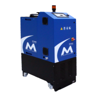
What to do if there is no adhesive output from VALCO MELTON D4-E Melting Machines?
- EErin VasquezAug 5, 2025
If you're experiencing no adhesive output from your VALCO MELTON Melting Machine, several factors could be at play. First, ensure the adhesive is adequately heated by verifying the temperature setting, checking the reservoir heater's power supply, and inspecting the fuses. If the pump isn't running, confirm the system is ready and check for blown fuses. Cold glue hoses or applicators can also be culprits, suggesting a hose replacement or checking the applicator's fuse and heater. Additionally, a clogged applicator or filter can impede output, necessitating service to the applicator system or replacement of the filter. Finally, a malfunctioning temperature control might be the issue, indicating it needs replacement.