6
Valcom, Inc.
5614 Hollins Road
Roanoke, VA 24019
540-563-2000 P.
540-362-9800 F.
www.valcom.com
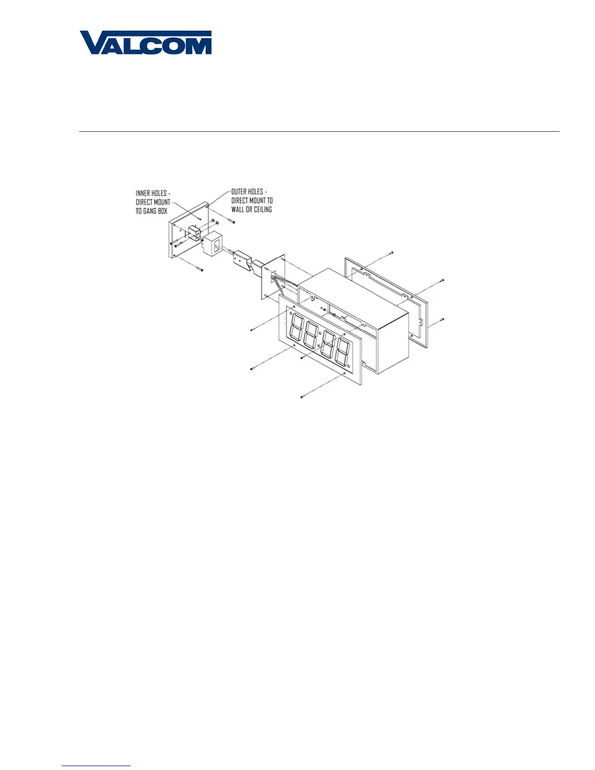
1. Screw hanger/mounting rod (included in the kit) into the crossbar (also included in the kit).
2. Insert wires through hanger/mounting rod.
3. Install crossbar using two (2) #6-32 screws into double gang box.
4. Mount the double mount box into the clock base using two (2) #6 nuts and Tooth Lockwasher #6. (The double mount can be
mounted either on the wall or on the ceiling).
5. Insert the two (2) locking hole plugs (0.187”) and the locking hole plug (0.562”) into the unused holes.
6. Insert double mount case onto the hanger/mounting rod.
7. Insert the support bracket onto the hanger/mounting rod.
8. Screw the two (2) nuts (included in the kit) onto hanger/mounting rod and secure the clock base to wall.
9. Connect the ground wire into the double mount box using the tooth lockwasher and machine screw nut (included in the kit).
10. Disconnect the red filter from the display panel.
11. Connect the wiring as shown on the wiring diagram.
12. IMPORTANT: If using a low voltage system (24 volt) make sure that the transformer is an isolated transformer.
13. Mount the display panel on one side of the double mount box using four (4) black machine screws (#6, included in the
kit). Make sure the switches are on the right side.
14. Snap the red filter into the display panel.
15. Repeat steps 9-13 for the second clock.
Metal Double Mount Installation