3. Installation
Erect fryer, to level rotate the setscrews underneath the front feet.
The fryer must not stand on combustible surfaces. Local safety regulations must be complied with.
N.B.: The slimline fryers V200 and V200T, as well as V250 and V250T, must not be freely erected (risk of
tipping over). They must be installed between 2 units of furniture, or they must be supported on the sides.
3.1 Electrical connection
Only experts may connect and commission the fryers.
Your mains data (voltage, current, fuse protection) must conform to the data on the fryer rating plate (The rating
plate is mounted on the inside of the door (Figs. 1 to 3 = D).
The electrical connection must conform to local regulations, essentially as follows :
- Fitting a mains plug on the connecting cable. Earth conductor = yellow/green, neutral conductor = blue
Phase sequence is immaterial.
- Any fixed connection must be made via a mains switch with all-pole isolation (min. contact distance 3 mm.).
- Before connection is made to the mains, check that the main switch "E" of the fryer is in the "0" position.
Never heat without oil !
3.2 Installation examples
A considerable amount of steam is generated when preparing chips. A good steam extractor is strongly
recommended.
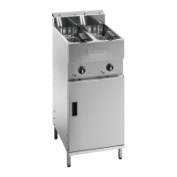
3.2.1 Installation example I (Fig. 1)
Wall socket [F] resistant to dripping water IP X2 or water spray IP X4
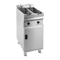
3.2.2 Installation example II (Fig. 2)
Fryer free-standing or next to cooking range. Connection column [H] with socket IP X2 or IP X4
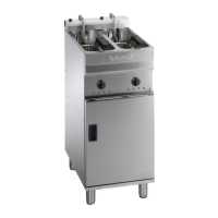
3.2.3 Installation example III (Fig. 3)
Connection box [J] with 3P+N isolating switch arranged above fryer. Cable permanently connected. Because of
the considerable steam generated the box must be watertight IP X5.
3.3 Cleaning
Pull the fryer forward [K] to clean the rear wall and bottom (Fig. 4). The cable must therefore be long enough to
do this.


 To Next Page