3
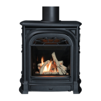
Mount the backing plate to the heater with screws in
the 4 slots (2 per side) of the plate; slide the plate in
desired position according to wall nish. Tighten the
screws.
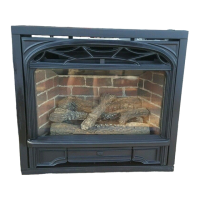
Fix the hanging brackets to the back side of the Inner
Casting as shown. Note the left/right orientation of the
brackets.
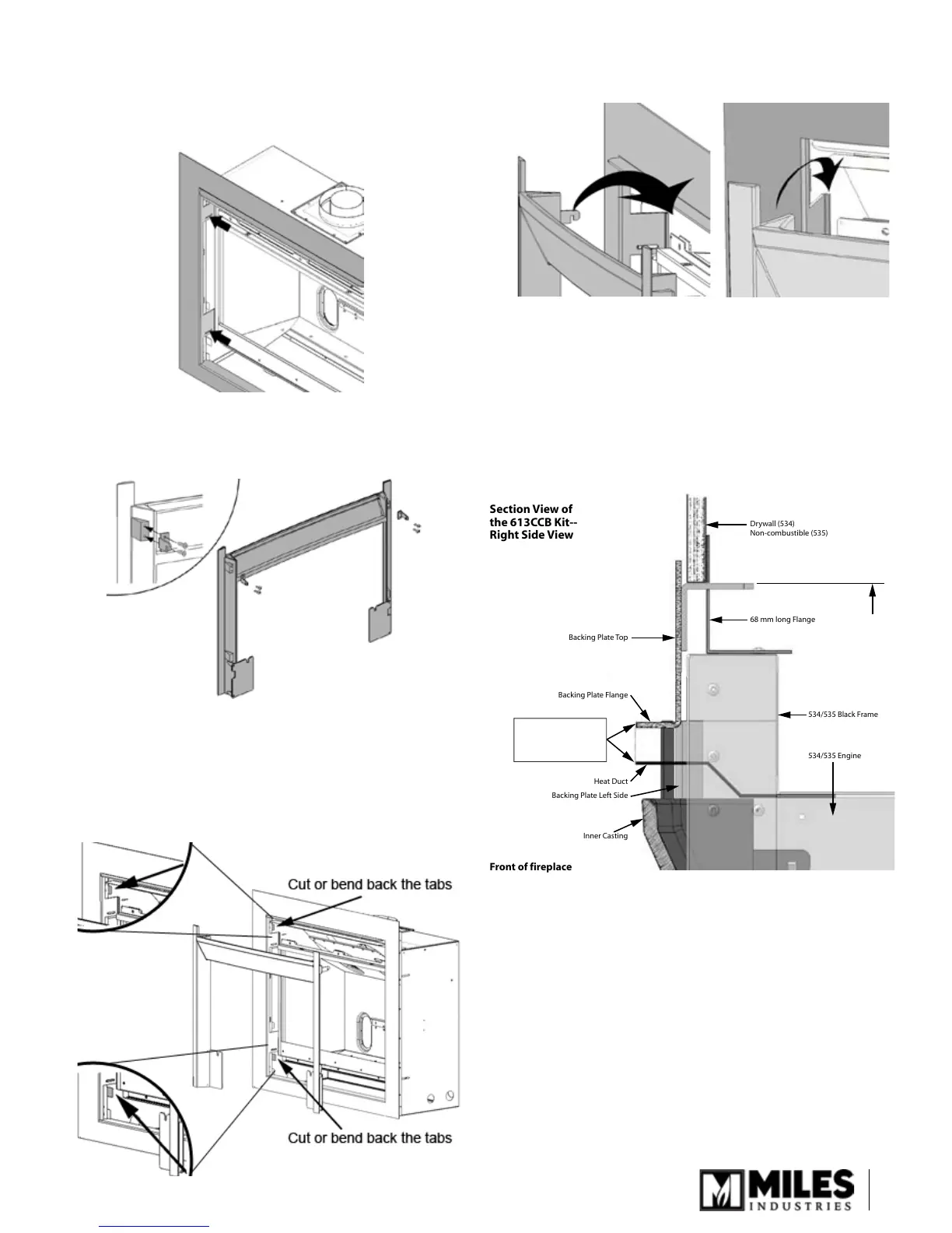
There are 4 tabs on the inside of the heater’s black
frame; those are intended for mounting other trims.
These tabs conict with the installation of the cast
front packaged with this kit. These 4 tabs must either
be cut off or bent back out of the way to allow the In-
ner Casting to install—see diagram.
3.
4.
5.
Hook the Inner Casting to the edge of the backing
plate anges as shown.
Drop cast iron fret into place by sliding the bolts into
the slots of the fret brackets on the inner casting.
Adjust bolts as necessary for a tight t.
Hook the ash pan to the fret.
Adjust top heat bafe by pulling it forward until it lines
up with the ange of the top part of the backing plate.
Tighten the screws.
6.
7.
8.
9.
Backing Plate Top
Backing Plate Flange
Heat Duct
Backing Plate Left Side
Inner Casting
534/535 Engine
534/535 Black Frame
68 mm long Flange
Drywall (534)
Non-combustible (535)
Front of fireplace
Section View of
the 613CCB Kit--
Right Side View
Heat duct must be
adjusted to be flush
with protuding flange
of backing plate
31-1/4”
from floor