2
Install the heater into framed cavity as described in these instructions and com-
plete the remainder of the installation as per instructions packed with heater.
Finish the wall up to the perimeter of the black frame at sides of the heater and to
the brackets on the rear of the backing plate, at the top. Ensure that the wall nish
is ush or slightly in front of the black frame. Allow for height of nished hearth or
oor, or steel backing plate will not install.
Remove the existing top heat bafe supplied with the heater and replace it with
the heat bafe supplied with this kit using the same 3 screws. Ensure the bafe
offsets upwards.
1.
2.
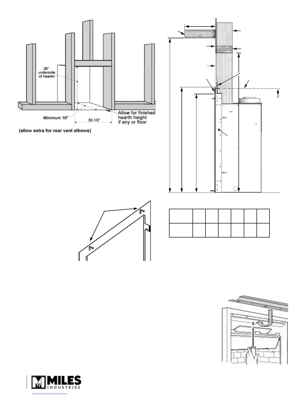
Installation
LH Frame
Header
36” from floor
to bottom
of header
Lower limit of
combustible
wall finish on 534
31-1/4”
from floor
Combustible
mantel or
shelf
“A”
“B”
31-3/4”
29-3/4”
534/535
Black Frame
Angle Support
Wall Finish
Non-combustible
material above
535 model only
613 Backing Plate
Mantel
depth A
2”
4” 6” 8” 10” 12”
Mantel
height B
32”
35” 38” 40” 42” 44”
Framing
Framing Cavity
Wall Finish Detail & Mantel Clearances
Approved for combustible oor under and in front of
the appliance.
Combustible wall nish may contact the sides of the
heater’s black frame.
Non-combustible wall nish may be required above the
heater, between the header and the backing plate—
see Wall Finish Detail & Mantel Clearances diagram.
•
•
•
Brackets on the rear of the backing plate to limit the
bottom height of:
the combustible wall nish
above the 534 heater,
or
the non-combustible
wall nish above the
535 heater.
•
•