28BREZZA60 INSTRUCTION AND MAINTENANCE MANUAL
1.7 Assembly conclusion
Assembly instructions
5
4e 6 8 8
4i
ØD
7
8 87
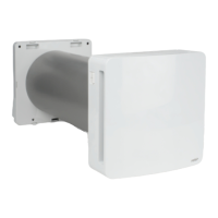
1) After the connection, carefully arrange the terminal box
and the cables in the proper compartment and insert the
ceramic heat exchanger (7) with related filters (8), placing it
in the middle of the recessed tube (6).
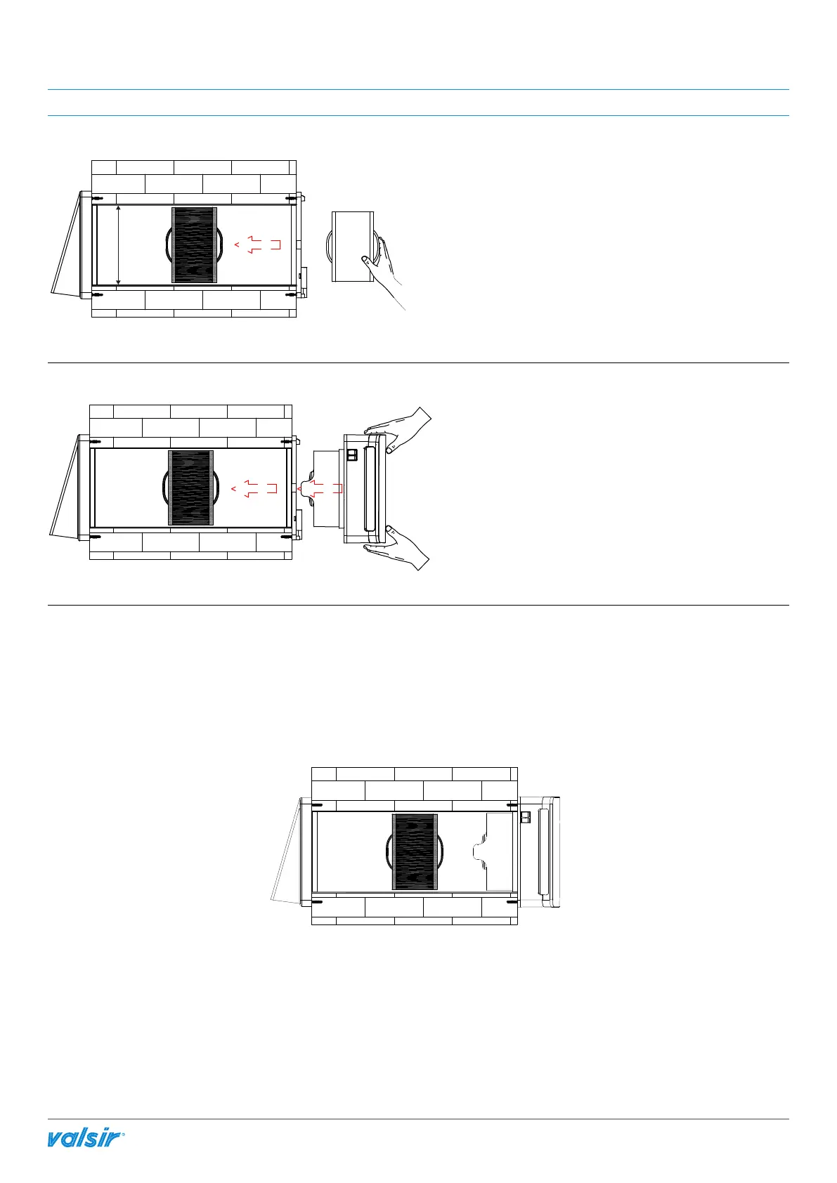
2) Fix the main unit (3), with its shutter (2) and the cosmetic
frontal cover (1) already assembled on it, on the internal wall-
mounting part (4i) until complete assembly.
Make sure to install the main unit on the wall placing all the
switches in the top left.
1.8 Maintenance
All maintenance operations must only be done by qualified personnel.
Before carrying out any cleaning or maintenance, disconnect the main supply.
Figure 1.8 Installed components positioning.
5
4e 6 8 8
4i
7
3
2
1
Once installed, the product must have all the components placed exactly as shown in the picture here above.
3
2
1
5
4e 6 8 8
4i
7