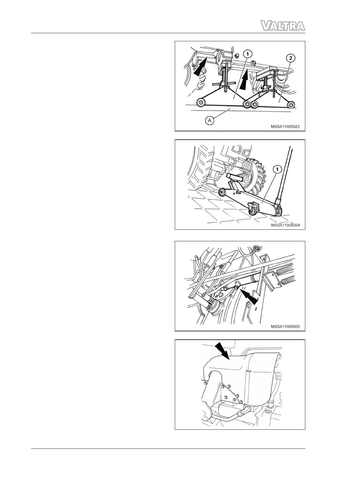
11. Place a rail (Equipment "A") under the tractor
and use two trolleys (1) and (2) with height
settings on the rails.
12. Position the trolley (1) under the engine and
the trolley (2) under the fuel tank (arrow),
adjusting them until they touch the housing
of the components.
GUID-51BFA88A-8091-4EDF-BF06-2C31FB7727E8-high.jpg [High]
Fig. 18
13. If the tractor is fitted with front weights,
place a hydraulic jack (1) 5 t) supported under
counterweights.
NOTE: Never remove the locking bolts from
the assemblies until the housings are
properly chocked.
GUID-9ECEEEA8-A82A-4790-8187-9267625130F4-high.jpg [High]
Fig. 19
14. Place the container on the right-hand side of
the tractor, below the drain plug, on the
suction pipe of the hydraulic system pump.
Remove the drain plug and completely drain
the oil.
15. After all of the oil has been drained, clean
and insert the drain plug and tighten it to a
torque of 25 N.m.
GUID-E0E59A81-AB08-4D1B-9AAF-D71EF195AC40-high.jpg [High]
Fig. 20
16. Loosen the connection for the high-pressure
hose supplying the hydraulic system, on the
side pump outlet.
: If necessary, remove the deflector plates
protecting the hydraulic pump.
GUID-1AE075B3-0FFE-4DBD-A237-D9FDAB72E4B7-high.jpg [High]
Fig. 21
1. Introduction
1-34
ACX2831410
 Loading...