Page 9
STEM ROTATION DIRECTION AND VALVE POSITION INDICATION
Typical valve hand wheels and levers require
80 lbf. (335N) of handle force to operate.
80 lbs. to
CLOSE
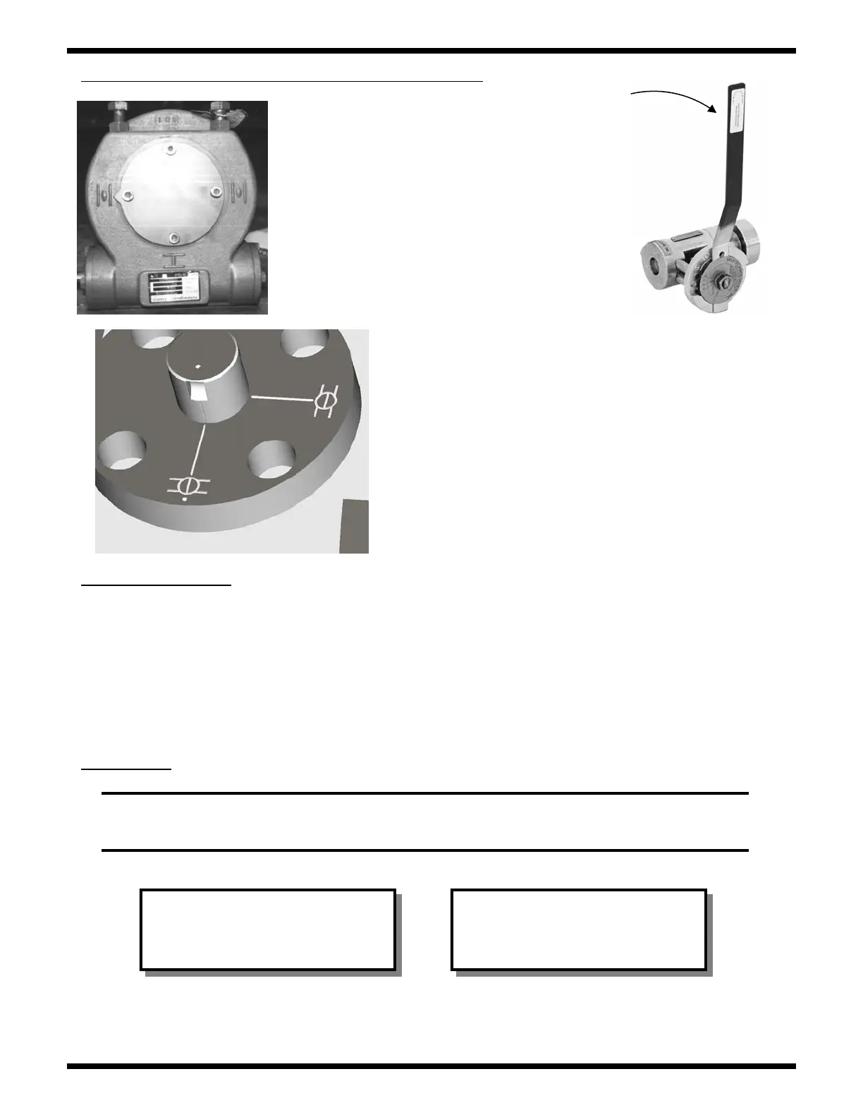
Lever operated are shown to be open when
the handle lies on the same axis as the valve
bore. The valve indicated closed when the
handle is at 90
o
to the valve bore.
ACTUATOR OPERATION
Valve actuators must be installed, operated and maintained as per their manufacturer’s written
instruction. In the event of a conflict between these instructions and those contained in this manual an
authorized ValvTechnologies distributor or to ValvTechnologies Houston facility should be contacted.
The lubricant of worm gear actuators should be inspected every three months and be replenished or
replaced if required.
On actuated and gear-operated valves an arrow
shows the valve position.
The stem, gland and ball (and in some instances the
drive sleeve) bear markings as shown to the left. The
marks will line up on the left of a closed valve, when
looking down on the stem and facing downstream.
All ValvTechnologies ball valves (unless spe-
cifically stated) are operated clockwise to
close and counter-clockwise to open.
CAUTION! During disassembly
particular care should be taken
not to damage mating, packing,
or sealing surfaces.
CAUTION! Packing must be re-
placed if gland nuts are loose.
Only approved ValvTechnolo-
gies packing shall be used.
MAINTENANCE
WARNING! DISASSEMBLY AND REPAIR OF VALVTECHNOLOGIES VALVE
ASSEMBLIES BY UNAUTHORIZED PERSONNEL MAY BE HAZARDOUS AND
NEGATE WARRANTIES.
DISASSEMBLY