VAMP Ltd Ethernet adapter
User’s manual
VEA 3CGi
1. General
Installed to 35mm DIN- RAIL
Steel plate case
Powered from the VAMP relay via serial cable (from the
LOCAL port of the relay) or from an external power supply
interface. There is a screw terminal (6 , see figure 1) for
connecting an external power supply.
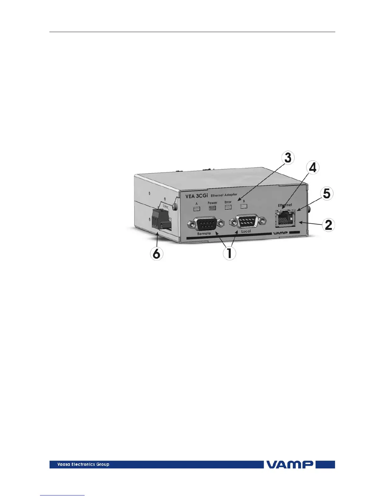
1.1. Front panel
Figure 1.1-1VEA 3CGi front panel
1. 2 serial ports : connection to VAMP relay (Local + Remote)
2. Ethernet port : 10 Mb/s, RJ-45 connector
3. 4 LED indicators:
Power: Powered by VAMP relay
Error: Internal error
A/B Future feature
4. Act: Communication active
5. Link: Ethernet link is active
6. External power supply and grounding interface:
Range: +12..24Vdc
Power:1W
Connection: Removable terminal block
Grounding help limit the effects of noise due to
electromagnetic interference (EMI) Run the ground
connection from the right most connector of the 3-
contact terminal block to the grounding surface prior to
connecting devices.
VMVEAi.EN001