Do you have a question about the Van Norman FG5000 and is the answer not in the manual?
Describes the warranty terms and conditions for the product.
Instructions for inspecting the machine upon delivery.
Emphasizes having the serial number ready for parts or service inquiries.
Lists and explains various safety pictograms and their meanings.
Detailed instructions for safe machine operation, including grounding and work area preparation.
Lists part numbers, amp service, and wire size for FG5000 models.
Lists part numbers, amp service, and wire size for FG10,000 models.
Details table diameter, capacity, motor, and travel specifications for FG5000.
Details table diameter, capacity, motor, and travel specifications for FG10,000.
Itemized list of standard parts included with the machine.
Lists specific optional parts for centering and coolant.
Lists various optional grinding wheels available.
Details the components of the VW/Universal Flywheel Kit.
Details the components of the optional dial indicator set.
Lists the individual components within the indicator bar kit.
Lists parts included in the optional radius cutter assembly.
Details the specific components of this centering cone set.
Lists the parts that make up the optional clutch tooling kit.
Details the components of this specialized centering and spacer set.
Lists components related to the ATP5000 transmission pump kit.
Details the components and purpose of the flywheel dowel pin puller kit.
Details the specific centering adapters included in this set.
Guidance on choosing grinding stones based on material and hardness.
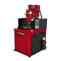
Identifies key machine parts and control elements.
Instructions for unpacking, removing packaging, and initial machine setup.
Steps for leveling the machine and installing the tool board.
Specific step for attaching the handle to the wheel dresser.
Instructions for adding lubricant to the machine's oil reservoir.
Procedure for using the depth gauge to check oil levels.
Steps for preparing and filling the coolant tank with additive and water.
Emphasizes the need for a qualified electrician for hookup.
Details connections for three-phase and single-phase hookups.
Instructions for checking the rotation of table and grinder motors.
Steps for correctly installing a grinding wheel.
Explains the process and reasons for dressing the grinding wheel.
Steps to prepare the machine for mounting a flywheel.
Instructions on using adapters and cones for accurate flywheel mounting.
Final checks and preparations before commencing grinding.
Instructions for operating the grinder manually.
Instructions for operating the grinder using the powerhead controls.
Steps for using the automatic grinding feature.
Techniques for surface finish and grinding recessed parts.
Detailed instructions for setting up and operating the optional radius cutter.
Information on oil level, type, and adjustment for the table bearing.
Guidance on lubricating the machine's column and leadscrew.
Specifies grease type, amount, and intervals for motor lubrication.
Details oil type, change intervals, and capacity for the gearbox.
Procedure for removing and cleaning the coolant tank.
Instructions for maintaining the E-Z Lock insert on the table spindle.
Procedure for adjusting the front-to-rear tilt of the grinding head.
Steps for adjusting the side-to-side tilt of the grinding head.
Describes the different mounting positions for the grinding head motor.
Instructions for adjusting the position of the head lock handle.
Method for adjusting and reducing backlash in the leadscrew.
Procedure to eliminate side-to-side movement in the grinding head column.
Exploded view diagram of the manual leadscrew assembly.
Exploded view diagram of the motor and associated drive components.
Exploded view diagram illustrating the grinding head assembly parts.
Exploded view diagram showing base and housing components.
Comprehensive list of all machine parts with numbers and quantities.
Diagram showing switch panel layout and identifying each switch.
Lists specific switch panel components based on machine model numbers.
Lists control box parts and wiring details across different machine models.
Provides electrical wiring schematics for various FG5000 and FG10,000 models.
| Brand | Van Norman |
|---|---|
| Model | FG5000 |
| Category | Grinder |
| Language | English |