Do you have a question about the Vanner LifeSine LSC12-1100 and is the answer not in the manual?
Describes the primary operation of converting DC to AC power.
Explains how to control the inverter remotely using external switches.
Details the energy-saving Load Demand feature and its application.
Explains the three-stage battery charging process and control.
Describes how the unit switches between shore power and inverter power.
Details how the unit limits shore power load by managing charger output.
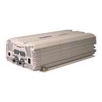
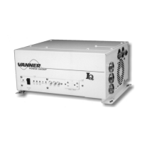
Identifies and describes components on the front panel of the unit.
Explains the status of LEDs for battery, load, system, and charger.
Details the function of DIP switches and the ON/OFF/REMOTE switch.
Identifies and describes components on the rear panel of the unit.
Covers general safety guidelines, cautions, and warnings for unit operation.
Details warnings and precautions regarding explosive gases and personal safety around batteries.
Covers safe placement, DC connection, and grounding instructions for the unit.
Instructions for inspecting the unit and its included accessory pack.
Covers unit placement, DC cabling, fusing, bonding, battery connection, and DIP switch settings.
Details remote control setup, troubleshooting, AC load connection, and final verification.
Details selecting location, routing cable, and securing the panel.
Explains the behavior of status LEDs on the LSCR and LSIR panels.
Step-by-step guide on how to operate the LifeSine inverter/charger unit.
Details common fault conditions, LED indicators, beeper states, and their solutions.
Addresses frequent user questions regarding symptoms and their solutions.
| Model | LSC12-1100 |
|---|---|
| Input Voltage | 12 VDC |
| Output Voltage | 110 VAC |
| Continuous Output Power | 1100 Watts |
| Frequency | 60 Hz |
| Cooling | Fan cooled |
| Operating Temperature | -20°C to 50°C |
| Peak Power Output | 2200 Watts |
| Efficiency | 90% |
| Protection Features | Overload, Over Temperature |