Do you have a question about the Vanner 20-1050CUL and is the answer not in the manual?
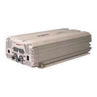
Converts 12 VDC battery power to 1050 Watts of 120 VAC modified sine wave power.
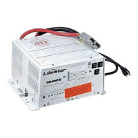
Multi-stage charger automatically charges and maintains battery integrity, reducing premature failure.
Details output power, surge capacity, input/output voltage, frequency, and waveform.
Specifies current draw for OFF, Load Demand, Full ON states, and frequency.
Details charging capacity, input voltage/current, and bulk/float voltages.
Covers GFCI outlet, AC input/output termination, temperature, cooling, chassis, dimensions, and weight.
Inspect the shipping container and equipment for loose or damaged parts.
Choose a location close to the battery, protected from weather, and with good air circulation.
Route negative and positive DC input cables from the inverter to the battery, protecting them as needed.
Install an inline fuse in the red, positive DC input cable within 18 inches of the battery.
Connect the chassis bonding lug to the vehicle chassis or earth ground using a suitable conductor.
Connect the black negative and red positive DC input cables to the battery terminals properly.
Choose the Load Demand option via the front panel Setup Switch to conserve battery energy.
Select the correct battery type (gel or flooded lead acid) using the front panel Setup Switch.
Choose between 55 Amps (High) or 15.0 Amps (Low) charging rate based on battery bank size.
Connect AC loads to the inverter GFCI receptacle for power.
Ensure all connections are tight and secure for optimal performance and safety.
Explains Steady Green, Single Blink Green, Double Blink Green for inverter status.
Describes Solid Red and Blinking Red for low battery conditions.
Details Solid Red (Overtemp) and Blinking/Solid Red (Overload) fault conditions.
Explains Blinking Yellow (High Charge) and Solid Green (Ready/Maintenance) for charger status.
Mount the IFM1 module in the vehicle's wiring harness, considering location and orientation.
Connect the 2 ft. interface cable between the inverter and the IFM1 module using RJ-11 and J1 connectors.
Connect the +12 V lead from the Module Disconnect Switch circuit to the inverter lockout Pin 1.
Wire the remote switch (p/n D06781) to IFM1 module pins 2-5, or install jumpers if no switch is used.
Connect the inverter remote status display panel wires to IFM1 module pins 6, 7, and 8.
Connect the charger remote display status panel wires to IFM1 module pins 9, 10, and 11.
Follow steps for mounting, identifying, splicing, and securing remote status display panels.
Explains LED status for inverter operational, standby, and load demand modes.
Describes red fault LED indicating shutdown due to low battery, overload, or overtemp.
Explains LED status for AC presence and charger modes (High Charge, Maintenance).
Describes red fault LED indicating charger shutdown due to low battery, overload, or overtemp.
Covers unit installation, vehicle startup, and turning on key switches.
Connect shore power and push the ON-OFF/RESET switch to the ON position.
Apply AC load, remove shore power to test inverter mode, and observe load demand status.
Addresses normal blinking on DC input connection or dipping voltage issues.
Troubleshoots issues with the ON lamp not lighting steadily or flashing.
Diagnoses problems when the ON lamp is illuminated but the AC load does not run.
Addresses the BATTERY LOW lamp illuminating when an AC load is applied.
Explains causes and solutions for Overtemp and Overload lamp illumination.
Diagnoses DC fuse blowing issues, particularly related to polarity.
| Input Voltage | 12 VDC |
|---|---|
| Output Voltage | 120 VAC |
| Continuous Output Power | 1000 Watts |
| Surge/Peak Output Power | 2000 Watts |
| Efficiency | 90% |
| Frequency | 60 Hz |
| Waveform | Modified Sine Wave |
| Cooling | Fan |
| Protections | Overload, Over Temperature, Short Circuit, Low Voltage |
| Input Current (Full Load) | 105 A |