Do you have a question about the Vanner VLT12-1000 and is the answer not in the manual?
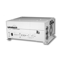
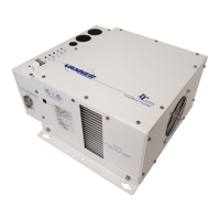
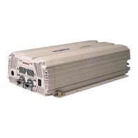
Lists available VLT Series inverter models and their configurations.
Details technical parameters like output, voltage, frequency, and dimensions for all models.
Lists key features of the VLT Series inverters, such as sine wave output and protection.
Explains the 'Load Demand Feature' and 'Load Demand Mode' for energy conservation.
Emphasizes reading and saving safety instructions before installation and use.
Lists general safety guidelines for operating the inverter, avoiding hazards like water and fire.
Warns about potential sparks and the risk of fire/explosion near batteries or flammable materials.
Provides guidelines for safely working near lead-acid batteries, including eye protection and handling acid.
Identifies DC input, remote control, ground lug, and cooling fans on the rear and sides.
Describes Battery Voltage, Load Watt, and Over Voltage indicators on the front panel.
Details Under Voltage, Over Temp, Overload, and general inverter status indicator lights.
Describes ON/OFF switch, dip switch, vents, mounting rails, and GFCI receptacle.
Instructions for inspecting the shipping container and equipment for damage.
Guidelines for selecting a mounting location, considering clearance and ventilation.
Discusses DC fuse requirements, NEC compliance, and wiring best practices.
Step-by-step guide for connecting DC cables, including fuse placement and grounding.
Procedure for wiring the AC output, emphasizing safety and code compliance.
Steps for safely starting up and testing the inverter after installation.
Monthly maintenance tasks to ensure continued reliability and safety of the inverter.
Initial checks to perform before troubleshooting specific inverter problems.
Lists common problems and their corresponding checks and solutions.
A table for recording monthly GFCI test results for safety.
| Model | VLT12-1000 |
|---|---|
| Type | Inverter |
| Input Voltage | 12 VDC |
| Output Voltage | 120 VAC |
| Output Waveform | Modified Sine Wave |
| Frequency | 60 Hz |
| Cooling | Fan Cooled |
| Output Power | 1000W |
| Peak Power Output | 2000W |
| Protection Features | Overload, Short Circuit |