8
Section 4: Installing the Inverter and Charger Remote Status Display Panels
Both the inverter and charger Remote Status Display Panels contain a red and green LED
indicator. On the inverter status panel, the green indicator light signifies the unit is ON or in
the Standby mode. On the charger status panel, the green light indicates the presence of shore
power or that the battery is being maintained at its current level. For both the inverter and
charger, the red, Fault LED indicator shows problems such as over temperature, output
overload, or low battery.
The panels have a sealed overlay which mounts easily on a flat surface, Each panel is
equipped with a 12-in. pigtail harness for easy installation. The following installation
procedure applies to both the inverter and charger panels:
Step 1: Select a location for the panel.
Identify the desired location for the inverter and charger panels.
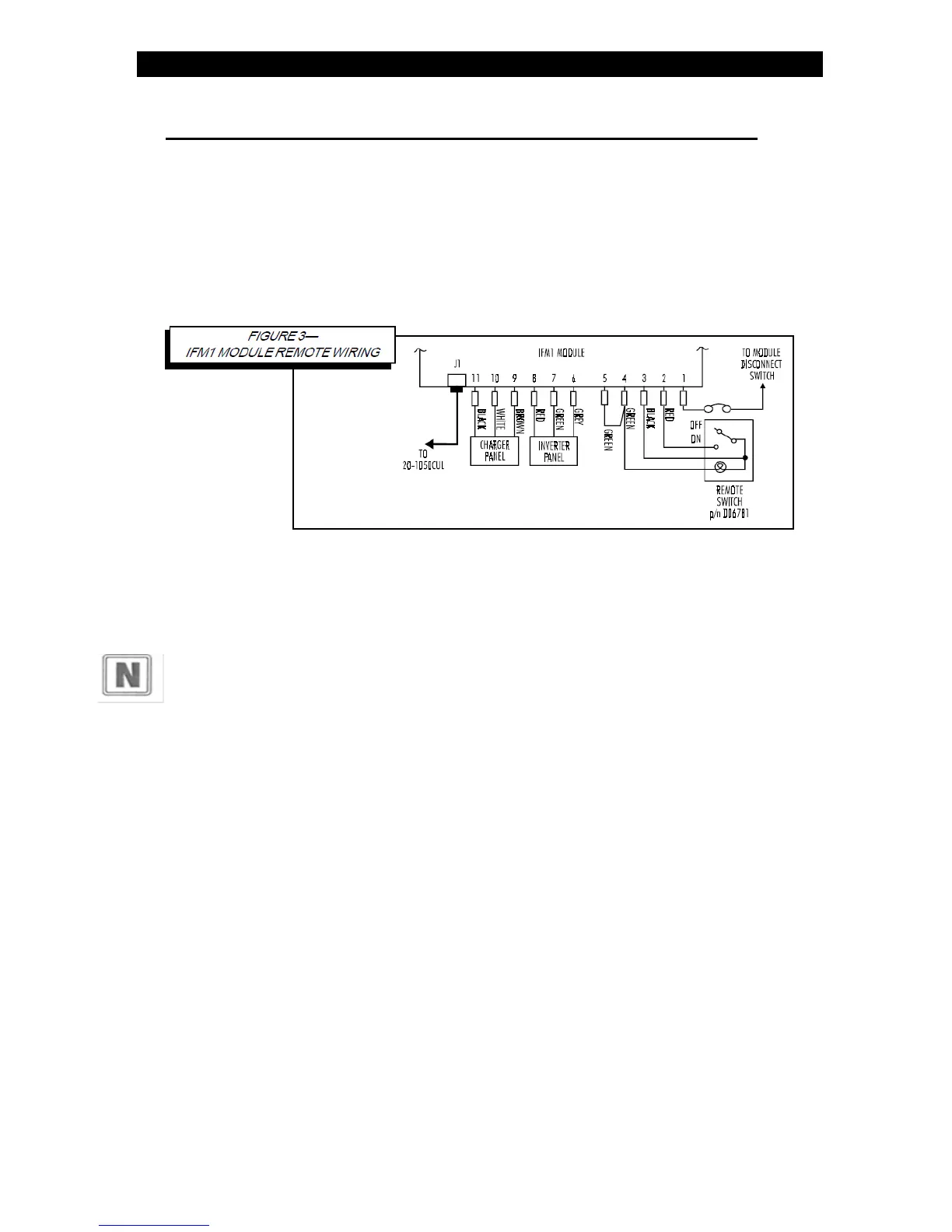
Step 2: Identify wires for installation.
Identify the gray, green, and red wires on the inverter panel and vehicle's electrical
system. Identify the brown, white, and black wires on the charger panel and the
vehicle's electrical system.
Step 3: Splice and arrange wires.
Splice together like-colored wires from the vehicle's electrical system to the status
panel using an insulated butt splice or equivalent. Carefully arrange the wires such
that the panel mounts flush against the surface to which it is mounted.
Step 4: Secure panels to surface.
Mount
the panels using #8 screws through the four holes in the panel