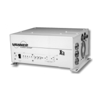
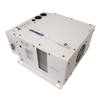
VANNER Incorporated
VLT Series True Sine Wave Inverter - Owner’s Manual
9
4. COMPONENT IDENTIFICATION and DESCRIPTION OF
OPERATION
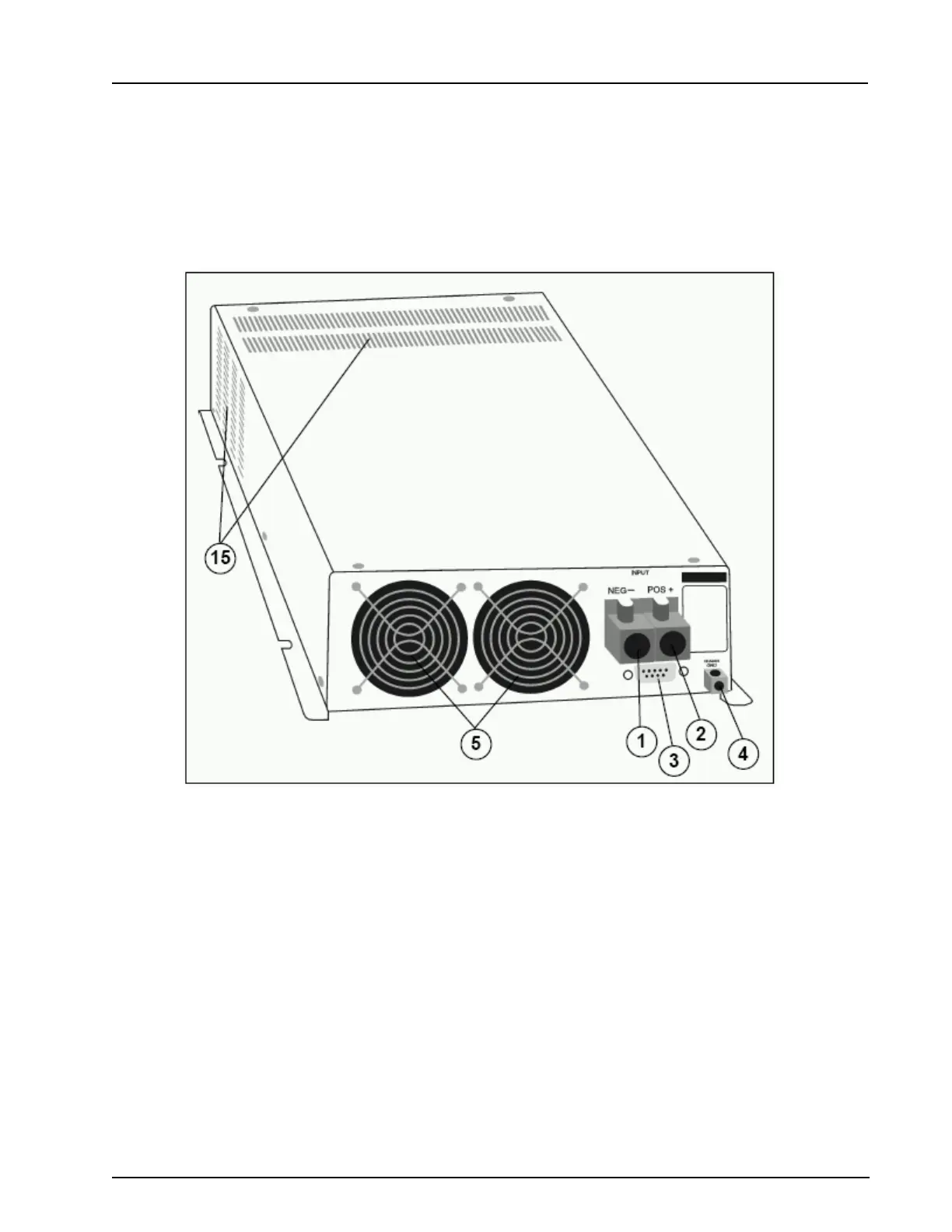
Figure 2 Inverter Top, Right Side & Rear View
(1) Rear entry for negative DC input cable
(2) Rear entry for positive DC input cable
(3) Rear entry for Remote Control RS 232 Connection
(4) Chassis Ground Bonding Lug
(5) Cooling Fans
Draw air in through intake vents on the top, sides and bottom of inverter and exhaust it out the back for the
purpose of cooling the unit. Fans will not continue running when the inverter goes to sleep.