F-550
2.3.1.1 Technical data
F-550 Unit Value
Length / length for transport mm 1835 / 1167
Width mm 600
Height / including centred handlebars mm 595 / 1030
Weight kg 56
Operating temperature °C from +5 to +30
Maximum cutting width / blade length cm / mm 58 / 537
Stubble height cm 4 – 9
Safe degree of incline
∠
10°
RPM
48
min
-1
1964
Blade peripheral speed m.s
-1
54
Drive speed km.h
-1
1,8 - 2,4
Machine area capacity
49
m
2
.h
-1
950 - 1300
Gearbox oil capacity l (litr) 0,025
Recommended gearbox oil API / SAE GL-4 (GL-5) / 90 (80W-90)
Table 3: F-550 technical data
2.3.1.2 Engine information
Any information about the engine that is not included in this manual is available on the engine manufacturer’s website.
Motor Unit Value
Model - HONDA GCV190A N2G7
50
Maximum engine RPMs (set) min
-1
3200 ± 100
Maximum engine incline / short-term
51
∠ 20° / 30°
Fuel tank capacity
52
l (litre) 0,91
Fuel gasoline (unleaded) Octane no. 91-95
53
Engine oil capacity l (litr) 0,55
Oil rating SAE / API 15W-40 / SJ or SH
Spark plug - NGK BPR6ES or BRISK LR15YC
Table 4: Basic engine information
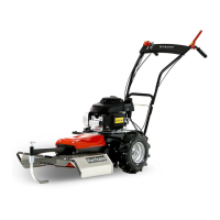
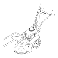
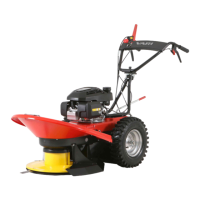
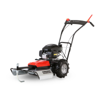
2.3.2 Description of machine and its components
The F-550 brush cutter frame (on
Pic. 3
) is made of a welded steel frame 11 from formed sheet metal, which all essential machine
components are attached to. The handlebars are mounted to the frame with screw connections 3 and their height may be adjusted into
six positions. All control elements ( 1 , 2 and 4 ) for safe control of the machine are ergonomically distributed along the handlebars.
The handle 12 is used to firmly grasp and direct the machine during operation. A wheel drive clutch lever 2 is located on the left
side of the handlebars, which controls the motion of the machine forward. On the right side is a tool drive clutch lever 1 equipped with
a safety lock to prevent accidental operation 16 , which turns the work tool (blade) drive on or off. If the operator releases the
handles in an emergency, both of the control levers return to the default position and the engine is disengaged from transmitting force. The
blade drive is equipped with an automatic braking device, which stops the blade
54
in the event of an emergency. Motor speed is controlled
by the throttle lever 4 . Motion is secured by wheels 15 with arrows pattern, which are driven by a worm-gear unit. It provides smooth
shifting of force to the wheel via a belt-driven clutch
(the machine moves forward without jerking)
. The wheel and blade drive transmission
part are covered by plastic housing 9 and 10 . The brake, blade drive clutch, and belt gears in front are also covered from above by a
plastic cover 9 connected by screws to the frame. Pressed on the shaft at the front of the frame is a blade holder with blade 7 . The
blade is fixed and sharp at the ends. The main deck comprises a cover 8 made from hot-dip galvanized
(HDG)
sheet metal, which except
for the front, spans further than the blade to prevent injury to the operator from flying parts of the mowed area. The deck is riveted from
several parts and screwed to the frame. A plastic shroud is fastened between the wheels. During operation, the machine is guided by a
swivel, height-adjustable spur 5 , which is attached to the front of the machine frame.
48
Actual revolutions of the non-laden work tool with calculated losses in the belt drive.
49
Machine area capacity rating depends on the type of cut vegetation.
50
More information about the engine including replacement part numbers can be found at www.honda-engines-eu.com
51
Short-term = within one minute
52
Measured according to the Society of Automotive Engineer (SAE) standard J1349
53
Due to the constantly increasing percentage of BIO constituents in fuel, use a fuel stabilizer.
54
Automatic brake is an active protective element that increases the safety of the machine.
22
05/2012
 Loading...