13.6 Replacing type TCW, TC8W cartridge seals (fig. 10, 13, 14, 15, 16)
- Empty the pump casing as described
in paragraph 8.
Attention: residual liquid may be
found inside the pump casing, head
and suction line; take all necessary
precautions if the liquid is hazardous
(inflammable, corrosive, poisonous,
infected, etc.)
- Unscrew the nuts (52) (fig. 10) and
remove the pump casing, taking
care not to damage the casing
gasket (43)
- Block the impeller (03) and remove
the self-locking impeller nut (33)
- Remove the impeller (03)
- Disconnect the flushing lines.
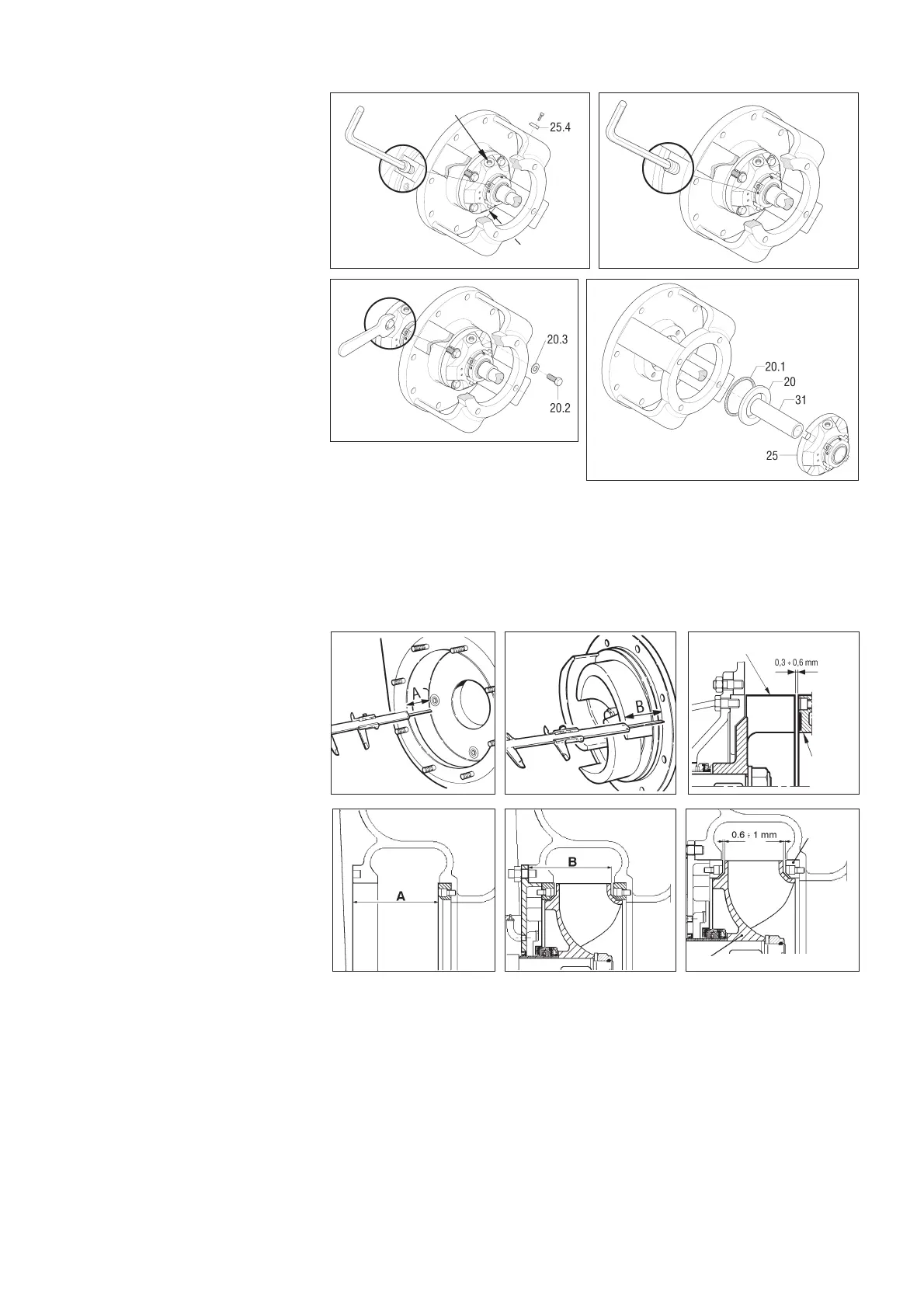
- Fix the seal lock setting plates (25.4)
in their seats (fig. 13)
- Loosen the grub screws of the shaft
sleeve (fig. 14)
- Unscrew the screws (20.2) which fix
the seal flange to the head (fig. 15)
- Remove the head (19)
- Remove the seal (25), the shaft
sleeve (31), the seal box (20) and the
gasket (20.1)
- If the gasket (20.1) is damaged, replace it
To assemble, proceed in reverse order
- To facilitate the initial assembly of the seal (fig. 18), smear a little oil on the shaft sleeve (31)
- Tighten the fixing screws (20.2) carefully (fig. 15) so as to avoid strain on the stationary seat of the seal
- Tighten the grub screws as far as they will go (fig. 14)
- Remove the setting plates (25.4) which hold the seal (fig. 13) and fix them in the appropriate holes in the flange so that they can be used
again to remove the seal
- Reconnect the flushing lines, begin flushing and bleed out air from the area around the seal. The seal must not run dry even for a few
moments.
13.7 Positioning the impeller with reference to the wear plate(s)
- In all models, the distance between
the top of the impeller blades and the
surface of the wear plate must be
between 0.3 - 0.6 mm (fig. 19). For
the 12" model, the distance between
the impeller and the front and rear
wear plates must be between 0.6 - 1
mm (fig. 22).
To achieve this, dimensions A and B
in figs. 17, 18, 20, 21 must be as
nearly as possible equal. To this end,
use the shims (25.2) (fig. 11)
supplied with spare mechanical
seals. These shims are used to move
the impeller further forward if it is too
far from the front wear plate or too
near the rear wear plate. The shims
should be mounted between the seal
support ring (25.1) (fig. 11) and the
impeller. Further adjustments can be
carried out using casing gaskets (and
rear wear plate gaskets on models
which fit these). The presence of the
casing gasket (43) (fig. 10) 0.5 mm
thick then creates the correct
distance (fig. 19).
13.8 Maintenance of the bearings (fig. 10)
The pump is supplied with the bearings already greased and does not require maintenance for the first 500 hours of operation.
The bearings in the bearing housing must be lubricated appropriately, avoiding the use of too much grease which can cause overheating
and, as a result, damage to the bearings.
13.9 Replacing the bearings
Empty the pump casing
Remove the casing, the head and the mechanical seal
Remove the flexible coupling hub and the shaft key
Remove the outer bearing cover (08)
Extract the shaft from the coupling side
Extract the bearings using a bearing extractor
To reassemble, proceed in reverse order
fig. 14
flushing hole
flushing
hole
wear
plate
impeller
fig. 17
fig. 18
fig. 19
impeller
wear
plates
fig. 21
fig. 22
fig. 20
9
fig. 13
fig. 15
fig. 16
 Loading...