18
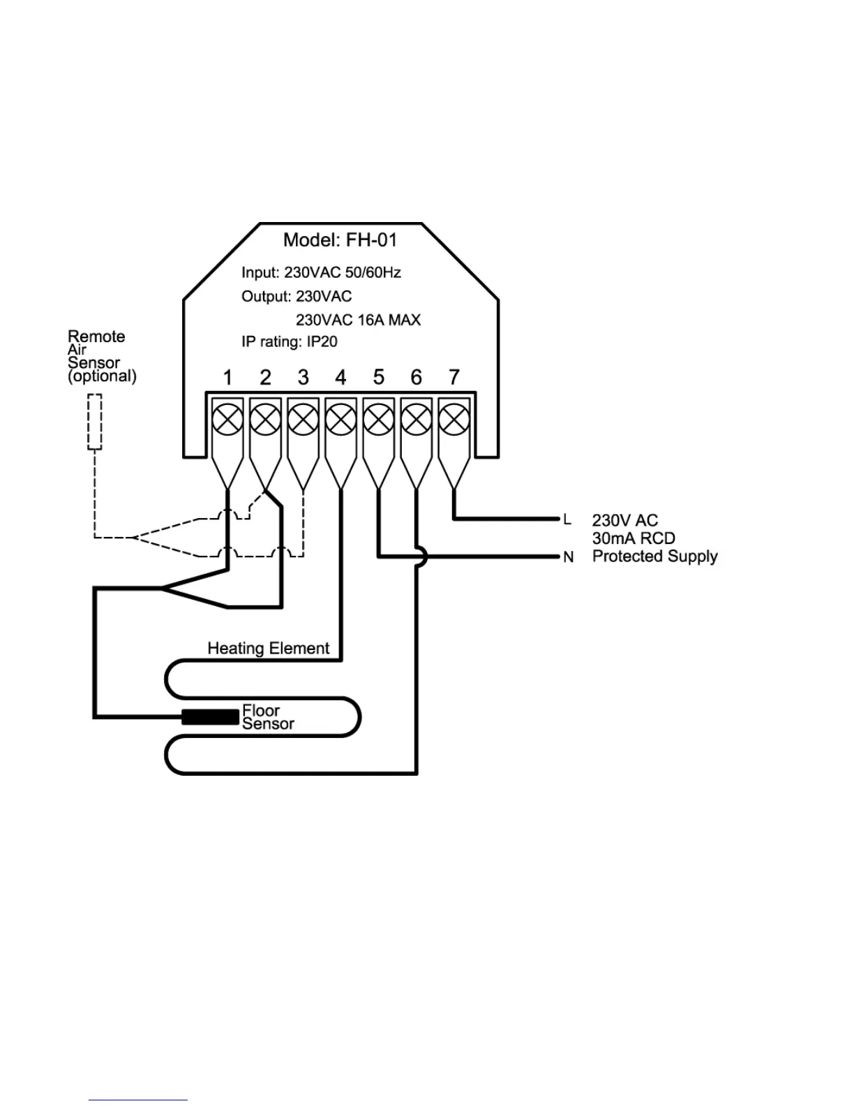
1. Floor Sensor Live
2. Sensor Neutral
3. Remote Air Sensor (Optional)
4. Heating Element Neutral
5. 230V Supply Neutral
6. Heating Element Live
7. 230V Supply Live
nb: generally underfloor heating elements & floor sensors are not
polarity conscious, as such can be connected to the live and neutral
either way round, unless insulation colouring dictates otherwise.
 Loading...