EP E series
11-03
10
Illustrations may differ from the actual product
Allowing for printing errors and errors on proofs
1 2 3 4 1 2 3 41 2
1 2 3 4
1
2
3
1
2
3
4 5
7
8
9
6
10
11
12
14
15
13
17
18
19
22
23
21
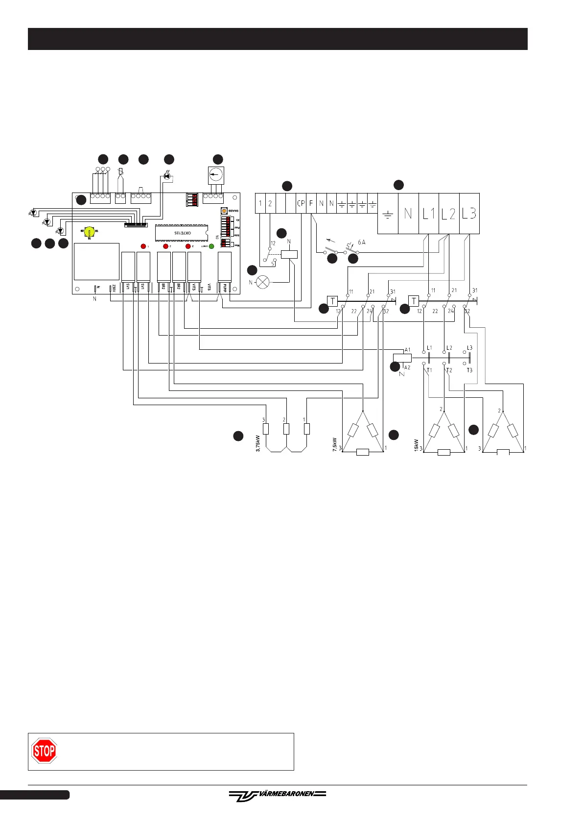
1. Connection of supply cable,
2. Circulation pump connection, 230V.
3. Current transformer.
4. Temperature sensor.
5. Connection for external block/remote control.
6. Power/status light.
7. Temperature setting.
8. PCB.
9. Indicator for power group one.
10. Indicator for power group two.
11. Indicator for power group three.
Wiring diagram - EP 26 E
12. Alarm, overheat protection triggered.
13. Alarm relay.
14. Control switch.
15. Control fuse.
17. Overheat protection, power groups one and two.
18. Overheat protection power group three.
19. Contactor, power group three.
21. Immersion heater for power group one.
22. Immersion heater for power group two.
23. Immersion heaters for power group three.
Electrical installation must be in accordance with the ap-
plicable regulations, under the supervision of an authorised
installer.