EasyManua.ls Logo

VDIAGTOOL VD10 - User Manual

VDIAGTOOL VD10
6 pages
Print Icon
To Next Page IconTo Next Page
Loading...
2
1.Safety Precautions and Warnings
To prevent personal injury or damage to vehicles and/or the scan
tool, read this instruction manual first and observe the following
safety precautions at a minimum whenever working on a vehicle:
Always perform automotive testing in a safe environment.
Do not attempt to operate or observe the tool while driving a vehicle. Operating
or observing the tool will cause driver distraction and could cause a fatal
accident.
Keep clothing, hair, hands, tools, test equipment, etc. away from all moving or
hot engine parts.
Wear safety eye protection that meets ANSI standards.
Operate the vehicle in a well ventilated work area: Exhaust gases are
Use extreme caution when working around the ignition coil, distributor cap,
ignition wires and spark plugs. These components create hazardous voltages
Put the transmission in PARK (for automatic transmission) or NEUTRAL
(for manual transmission) and make sure the parking brake is engaged.
Keep the scan tool dry, clean, free from oil/water or grease. Use a mild
detergent on a clean cloth to clean the outside of the scan tool, when Necessary.
Keep a fire extinguisher suitable for gasoline/chemical/electrical fires nearby.
Don't connect or disconnect any test equipment while the ignition is on or the
engine is running.
when the engine is running.
Poisonous.
3
2.General Information
2.1 On-Board Diagnostics (OBD) II
2.2 Diagnostic Trouble Codes (DTCs)
1) Whether the Malfunction Indicator Light (MIL) is commanded 'on' or 'O';
2) Which, if any, Diagnostic Trouble Codes (DTCs) are stored;
3) Readiness Monitor status.
The first generation of On-Board Diagnostics (called OBD I) was developed by
the California Air Resources Board (CARB) and implemented in 1988 to monitor
some of the emission control components on vehicles. As technology evolved and
the desire to improve the On-Board Diagnostic system increased, a new generation
of On-Board Diagnostic system was developed. This second generation of
The OBD II system is designed to monitor emission control systems and key
engine components by performing either continuous or periodic tests of specific
components and vehicle conditions. When a problem is detected, the OBD II system
turns on a warning lamp (MIL) on the vehicle instrument panel to alert the driver
typically by the phrase “Check Engine” or “Service Engine Soon”. The system will
also store important information about the detected malfunction so that a
technician can accurately find and fix the problem. Here below follow three pieces
OBD II Diagnostic Trouble Codes are codes that are stored by the on-board
computer diagnostic system in response to a problem found in the vehicle. These
codes identify a particular problem area and are intended to provide you with a
guide as to where a fault might be occurring within a vehicle. OBD II Diagnostic
Trouble Codes consist of a five-digit alphanumeric code. The first character, a letter,
identifies which control system sets the code. The other four characters, all
numbers, provide additional information on where the DTC originated and the
operating conditions that caused it to be set. Below is an example to illustrate the
On-Board Diagnostic regulations is called "OBD II".
of such valuable Information:
structure of the digits:
1
1. Safety Precautions and Warnings
2.1 On-Board Diagnostics (OBD) II
2.2 Diagnostic Trouble Codes (DTCs)
2.3 Location of the Data Link Connector (DLC)
2.4 OBD II Readiness Monitors
2.5 OBD II Monitor Readiness Status
2.6 OBD II Definitions
3.Using the Scan Tool
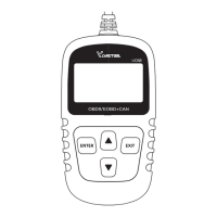
3.1 Tool Description - OBD VD10
3.2 Specifications
3.3 Included
3.4 Welcome
3.5 Battery Tester
3.6 Setup
3.7 About
From the About menu, show the software version, hardware version
and serial NO of product
........................................................................................8
..................................................................................................................9
..........................................................................................................................9
.........................................................................................................................9
................................................................................................................10
.............................................................................................................................10
.............................................................................................................................11
..................................................................................................................12
.................................................................................................................14
.......................................................................................................................16
......................................................................................................17
...............................................................................................................17
...................................................................................................................18
2.General Information
4.OBD II Diagnostics
4.1 Read Codes
4.2 Erase Codes
4.3 Live Data
4.4 View Freeze Frame
4.5 I/M Readiness
4.6 Vehicle Info
5.Warranty and Service
5.1 Limited One Year Warranty
5.2 Service Procedures
...................................2
..........................................................3
......................................................................................3
.................................................................................3
...................................................................4
...........................................................................................5
..................................................................................6
...........................................................................................................6
.........................................................8
...........................................................................................11
.........................................................12
.....................................................20
...........................................................................................20
......................................................................................................20
Table of Contents
VD10 OBDII
User’s Manual
Question and Answer IconNeed help?

Do you have a question about the VDIAGTOOL VD10 and is the answer not in the manual?

Summary

Safety Precautions and Warnings

General Information

On-Board Diagnostics (OBD) II

Explains the evolution and purpose of the OBD II system for vehicle emission monitoring.

Diagnostic Trouble Codes (DTCs)

Explains DTCs, their structure, and purpose in identifying vehicle faults.

Location of the Data Link Connector (DLC)

Describes the location of the vehicle's standardized 16-cavity diagnostic connector.

OBD II Readiness Monitors

Explains indicators for emissions component evaluation and readiness status.

OBD II Monitor Readiness Status

Details how the system indicates completed emissions system tests.

OBD II Definitions

Provides definitions for key OBD II terms like PCM, MIL, and DTCs.

Using the Scan Tool

Tool Description - OBD VD10

Details the physical components and buttons of the VD10 scan tool.

Specifications

Lists technical specifications like display, temperature, and dimensions.

Included

Lists the items included in the scan tool package.

Welcome

Initial welcome message and instruction to turn on ignition.

Battery Tester

Instructions on how to use the battery testing function.

Setup

Instructions for configuring the scan tool settings.

OBD II Diagnostics

Read Codes

Instructions on how to read stored and pending diagnostic trouble codes.

Erase Codes

Steps to clear diagnostic trouble codes from the vehicle's ECU.

Live Data

Instructions to view real-time vehicle sensor data and system status.

View Freeze Frame

How to view vehicle operating conditions recorded during an emission fault.

I;M Readiness

Checks if emission-related systems are ready for inspection.

Vehicle Info

Instructions to retrieve vehicle identification and calibration data.

Warranty and Service

Limited One Year Warranty

Details the terms and limitations of the product's one-year warranty.

Service Procedures

Provides contact information for service or repair inquiries.

Overview

The VD10 OBDII User's Manual describes a diagnostic scan tool designed for automotive testing. This device, identified as the VD10 OBDII, is used to interface with a vehicle's On-Board Diagnostics (OBD II) system to read and clear trouble codes, view live data, and assess the status of various emission control systems.

Function Description:

The primary function of the VD10 OBDII is to provide diagnostic information from a vehicle's On-Board Diagnostics (OBD II) system. OBD II is a standardized system designed to monitor emission control systems and key engine components through continuous or periodic tests. When a problem is detected, the OBD II system illuminates a Malfunction Indicator Light (MIL) on the vehicle's instrument panel (often labeled "Check Engine" or "Service Engine Soon") and stores Diagnostic Trouble Codes (DTCs). The VD10 OBDII allows users to:

  • Read Codes: Retrieve stored (hard codes) and pending (maturing codes) DTCs. Hard codes indicate emission-related faults that cause the MIL to illuminate, while pending codes suggest problems detected during the current or last driving cycle that are not yet considered serious enough to trigger the MIL. The tool displays the DTCs along with their definitions, and for manufacturer-specific codes, it prompts the user to select the vehicle make to view relevant definitions.
  • Erase Codes: Clear DTCs from the vehicle's Powertrain Control Module (PCM) memory. This function is performed with the ignition on and engine off. Users are advised to retrieve and record trouble codes before clearing them and to re-check for codes afterward to ensure the problem is resolved.
  • View Live Data: Access real-time data streams from the vehicle's computer. This includes values such as vehicle speed (VSS), fuel system status (FUELSYS1), engine load percentage (LOAD_PCT), engine coolant temperature (ETC), short-term fuel trim (SHRTFT1), and engine revolutions per minute (RPM). This data helps in diagnosing problems by showing the operating conditions of various sensors, switches, and actuators.
  • View Freeze Frame: Display a snapshot of the vehicle's operating parameters at the moment an emission-related fault occurred. This data, which may include engine RPM, vehicle speed, airflow, engine load, fuel pressure, fuel trim value, engine coolant temperature, and ignition timing advance, helps technicians understand the conditions under which a fault was set.
  • I/M Readiness: Check the status of Inspection and Maintenance (I/M) Readiness Monitors. These monitors indicate whether the vehicle's emission-related systems have completed their diagnostic tests and are ready for I/M testing. The tool shows the status of continuous monitors (Misfire, Fuel System, Comprehensive Components) and non-continuous monitors (EGR System, O2 Sensors, Catalyst, Evaporative System, O2 Sensor Heater, Secondary Air, Heated Catalyst, A/C System). The status can be "OK" (test completed), "INC" (incomplete/not tested), or "N/A" (not applicable). This feature is crucial for confirming repairs and preparing for emissions inspections.
  • Vehicle Info: Retrieve vehicle information such as the Vehicle Identification Number (VIN), Calibration ID (CID), and Calibration Verification Number (CVN).
  • Battery Tester: A dedicated function to test the vehicle's battery, displaying the current voltage.

Important Technical Specifications:

  • Display: Backlit, 128 x 64 pixel display with contrast adjustment for clear readability.
  • Operating Temperature: 0 to 60°C (32 to 140°F).
  • Storage Temperature: -20 to 70°C (-4 to 158°F).
  • External Power: The device is powered by the vehicle's battery, requiring 8.0 to 18.0 V.
  • Dimensions: Length: 70mm, Width: 22mm, Height: 126mm.
  • Connectivity: Connects to the vehicle's 16-pin Data Link Connector (DLC) via an OBD II connector.
  • Protocols: Supports OBDII/EOBD+CAN protocols, ensuring compatibility with a wide range of vehicles.

Usage Features:

  • User Interface: The tool features a simple interface with an LCD display and navigation buttons: ENTER, EXIT, UP SCROLL, and DOWN SCROLL.
    • ENTER Button: Confirms a selection or action from a menu.
    • EXIT Button: Cancels a selection, returns to the previous menu, or exits the DTC Lookup screen.
    • UP/DOWN SCROLL Buttons: Navigate through menu and submenu items, and scroll through multiple screens of retrieved data.
  • Setup Menu: Allows users to configure settings such as language and unit of measure (English/Metric).
  • Welcome Screen: Displays a welcome message upon startup, prompting the user to turn on the ignition and press ENTER to proceed.
  • Error Handling: Provides clear messages for communication failures (e.g., "LINKING ERROR!") and guides users through troubleshooting steps.
  • DTC Display: Shows the control module number, sequence of DTCs, total number of codes detected, and the type of codes (Generic or Manufacturer specific) on the upper right-hand corner of the display.
  • Abbreviation Descriptions: For Live Data and I/M Readiness, the tool allows users to view detailed descriptions of abbreviations by pressing the ENTER button.
  • Vehicle Manufacturer Selection: When manufacturer-specific codes are found, the tool prompts the user to select the vehicle's make from a list (e.g., Acura, Alfa Romeo, Audi/VW, Bentley, BMW, Buick) to view relevant DTC definitions. An "Other" option is available if the manufacturer is not listed.

Maintenance Features:

  • Limited One-Year Warranty: The product is warranted against defects in materials and workmanship for one year from the date of delivery. The warranty does not cover abuse, alteration, or misuse. The exclusive remedy for defects is repair or replacement.
  • Service Procedures: Users are advised to contact their local store, distributor, or visit the manufacturer's website (www.vdiagtool.com) for questions or if the scan tool needs repair.
  • Cleaning: The manual recommends keeping the scan tool dry, clean, and free from oil, water, or grease. A mild detergent on a clean cloth can be used for cleaning the exterior.
  • Safety Precautions: The manual emphasizes several safety precautions to prevent personal injury or damage to the vehicle or tool:
    • Always perform automotive testing in a safe environment.
    • Do not operate or observe the tool while driving.
    • Wear safety eye protection.
    • Keep clothing, hair, hands, tools, and test equipment away from moving or hot engine parts.
    • Work in a well-ventilated area due to poisonous exhaust gases.
    • Exercise caution around ignition components due to hazardous voltages.
    • Ensure the transmission is in PARK (automatic) or NEUTRAL (manual) and the parking brake is engaged.
    • Keep a fire extinguisher nearby.
    • Do not connect or disconnect test equipment while the ignition is on or the engine is running.

The VD10 OBDII is a comprehensive diagnostic tool designed for both professional technicians and DIY enthusiasts, offering essential functionalities for monitoring and troubleshooting vehicle emission systems.

VDIAGTOOL VD10 Specifications

General IconGeneral
BrandVDIAGTOOL
ModelVD10
CategoryMeasuring Instruments
LanguageEnglish