LVP603
LVP603
LVP603
LVP603 User
User
User
User
’
’
’
’
s
s
s
s Manual
Manual
Manual
Manual
---------------------------------------------------------------------------------------------------
---------------------------------------------------------------------------------------------------
---------------------------------------------------------------------------------------------------
---------------------------------------------------------------------------------------------------
LED
LED
LED
LED VIDEO
VIDEO
VIDEO
VIDEO PROCESSOR
PROCESSOR
PROCESSOR
PROCESSOR
13
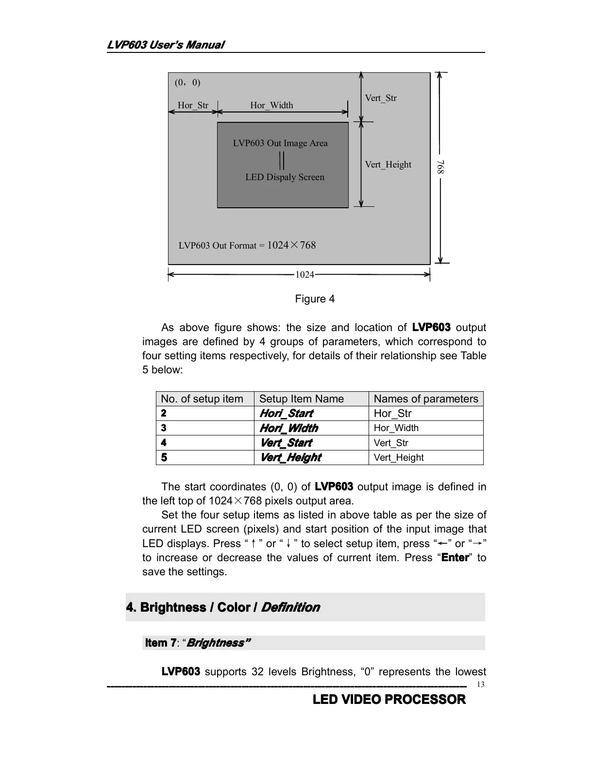
(0 , 0)
Hor_Str Hor_Width
Vert_Str
Vert_Height
LED Dispaly Screen
LVP603 Out Format = 1024 × 768
LVP603 Out Image Area
1024
768
Figure 4
As above figure shows: the size and location of LVP603
LVP603
LVP603
LVP603 output
images are defined by 4 groups of parameters, which correspond to
four setting items respectively, for details of their relationship see Table
5 below:
No. of setup item Setup Item Name Names of parameters
2
2
2
2
Hori_Start
Hori_Start
Hori_Start
Hori_Start
Hor_Str
3
3
3
3
Hori_Width
Hori_Width
Hori_Width
Hori_Width
Hor_Width
4
4
4
4
Vert_Start
Vert_Start
Vert_Start
Vert_Start
Vert_Str
5
5
5
5
Vert_Height
Vert_Height
Vert_Height
Vert_Height
Vert_Height
The start coordinate s (0, 0) of LVP603
LVP603
LVP603
LVP603 output image is defined in
the left top of 1024 × 768 pixels output area.
Set the four setup items as listed in above table as per the size of
current LED screen (pixels) and start position of the input image that
LED displays. Press “ ↑ ” or “ ↓ ” to select setup item, press “ ← ” or “ → ”
to increase or decrease the values of current item. Press “ Enter
Enter
Enter
Enter ” to
save the settings.
4.
4.
4.
4. Brightness
Brightness
Brightness
Brightness /
/
/
/ Color
Color
Color
Color /
/
/
/
Definition
Definition
Definition
Definition
Item
Item
Item
Item 7
7
7
7 : “
Brightness
Brightness
Brightness
Brightness ”
”
”
”
LVP603
LVP603
LVP603
LVP603 supports 32 levels Brightness, “ 0 ” represents the lowest