EasyManua.ls Logo

Vechline 1012 - User Manual

Vechline 1012
4 pages
Print Icon
To Next Page IconTo Next Page
Loading...
PWM Solar Charge Controller
User manual
Read these
instructions carefully
before use and keep
it safe for future
reference.
1012 / 2024
Question and Answer IconNeed help?

Do you have a question about the Vechline 1012 and is the answer not in the manual?

Summary

General Information

Features and Mounting

Indicators, Descriptions and Operations

Charging Status LED Indicator

Describes the meaning of the charging status LED indicator states.

Battery Status LED Indicator

Describes the meaning of the battery status LED indicator states.

Radix Point of Digital tube (Load indicator)

Describes the meaning of the digital tube radix point indicator states.

Operation

Explains how to operate the charge controller using the digital tube and button.

Troubleshooting

Technical Specifications

Disclaimer

Overview

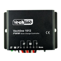
The Vechline 1012/2024 series PWM Solar Charge Controller is an advanced digital device designed for managing solar power systems. It operates fully automatically and is suitable for extreme environments due to its robust design and IP67 protection.

Function Description

The primary function of this controller is to regulate the charging of batteries from solar modules using Pulse Width Modulation (PWM) technology. This method is highly efficient, extending battery life and improving overall solar system performance. The controller also manages the load connected to the system, offering various operational modes.

Key protective features include:

  • Electronic protection: Safeguards against overcharging, over-discharging, overload, short circuits, and reverse polarity from the solar module.
  • Automatic day/night recognition: The controller automatically detects day and night conditions to manage load operation.

Important Technical Specifications

The Vechline 1012/2024 series offers two models with differing current capacities:

Item 1012 2024
Nominal system voltage 12/24VDC Auto 12/24VDC Auto
Max. PV input voltage 50V 50V
Rated current 10A 20A
Equalize Voltage 14.8V(12V); 29.6V(24V) 14.8V(12V); 29.6V(24V)
Boost Voltage 14.4V(12V); 28.8V(24V) 14.4V(12V); 28.8V(24V)
Float Voltage 13.7V(12V); 27.4V(24V) 13.7V(12V); 27.4V(24V)
Low Voltage Reconnect Voltage 12.6V(12V); 25.2V(24V) 12.6V(12V); 25.2V(24V)
Low Voltage Disconnect Voltage 11.2V(12V); 22.4V(24V) 11.2V(12V); 22.4V(24V)
Self-consumption 12V: ≤4.58mA; 24V: ≤6.01mA 12V: ≤4.58mA; 24V: ≤6.01mA
Temperature compensation coefficient -5mV/°C/2V (25℃) -5mV/°C/2V (25℃)
Working temperature -35℃ ~ +50°C -35℃ ~ +50°C
Enclosure IP67 IP67
Overall dimension 108.5mm×75mm×25.6mm 108.5mm×75mm×25.6mm
Mounting dimension 100.5mm 100.5mm
Mounting hole size Φ5 Φ5
Power cable PV/BAT/LOAD:4.0mm² PV/BAT/LOAD:6.0mm²
Net weight 410g 435g

Usage Features

The controller features an industrial design, making it suitable for a wide range of applications. User interaction is simplified through a single-key operation and a digital tube display for settings.

Indicators and Operations:

  • Charging Status LED:
    • Green (Solid): Normal charging.
    • Green (Fast Flashing): Over voltage.
  • Battery Status LED:
    • Green (Solid): Normal battery status.
    • Green (Slowly Flashing): Battery full.
    • Orange (Solid): Under voltage.
    • Red (Solid): Over discharged.
  • Radix Point of Digital Tube (Load indicator):
    • Red (Solid): Load ON.
    • Red (Slowly Flashing): Over Load.
    • Red (Fast Flashing): Short Circuit.

Load Work Modes: The digital tube displays the load work mode, which can be configured using a single key.

  • Manual Control: Allows manual switching of the load ON/OFF via the button.
  • Light ON/OFF: The load turns on at night and off during the day.
  • Light ON + Timer: The load turns on at night and stays on for a specified duration (1-13 hours).
  • Test Mode (Default): Similar to Light Control Mode but without the 10-minute delay.

Configuration Method:

  1. To enter configuration mode, disconnect the PV or connect the PV (Voltage<5V) until the digital tube point illuminates. It will turn off if PV voltage is >6V.
  2. The key can be used to switch the load ON/OFF (manual control) or clear faults.
  3. Press and hold the button for over 5 seconds to enter browsing mode. Click the button to cycle through parameters.
  4. Release the key when the desired value is displayed. After 15 seconds, the digital tube will stop flashing, and the setting will be saved.

Mounting:

  1. Connect components in the specified sequence: always connect the battery first, paying attention to polarity (+ and -).
  2. After connecting the battery, check if the battery indicator is green. If not, troubleshoot according to chapter 4.
  3. Install the battery fuse as close to the battery as possible, ideally within 150mm.

Maintenance Features

The controller is designed for reliability, but troubleshooting steps are provided for common issues:

  • Charging LED off during daytime (PV array disconnection): Check PV and battery wire connections for correctness and tightness.
  • Battery indicator green fast flashing (Battery voltage higher than over voltage disconnect):
    1. Disconnect the solar array and measure battery voltage.
    2. Consider changing the controller or battery if issues persist.
  • Battery LED indicators red and loads not working (Battery over discharged): The controller automatically cuts off output. The LED indicator will return to green once the battery is fully charged.
  • Radix point of digital tube fast flashing and load not working (Short circuit): Clear the short circuit. Reactivation occurs after a 10-second delay for the first instance. For subsequent occurrences, press the key to clear the error, and the controller will resume operation after 3 seconds or a restart.
  • Radix point of digital tube slowly flashing and load not working (Over load): Reduce the number of electric equipment. If load power exceeds 1.25-1.5 times, 1.5-2 times, or 2 times the nominal value, the controller will automatically close loads in 60, 5, or 1 second, respectively. Press the key to clear the error, and the controller will resume operation after 3 seconds or a restart.

Warranty Disclaimer: The warranty does not cover damages resulting from improper use, unsuitable environment, exceeding rated current/voltage/power, operating outside specified temperature limits, unauthorized disassembly/repair, or damage due to natural elements (e.g., lightning) or during transportation/shipment.

Vechline 1012 Specifications

General IconGeneral
BrandVechline
Model1012
CategoryController
LanguageEnglish

Related product manuals