Doc: 70-00-0958A V1.0, 20221102 © Vector Controls GmbH, Switzerland Page 18-34
Subject to change without notice www.vectorcontrols.com
5.6.2 Application modes: Valve control diagrams
Detailed explanation of Comfort and Economy temperature set points are given in chapter 5.7 Set points, page 22.
Detailed explanation of on/off or 3-position valve control are given in chapter 5.8 Control settings, page 24.
Detailed explanation of auto heat/cool changeover are given in chapter 5.9 Temperature and digital inputs, page 28.
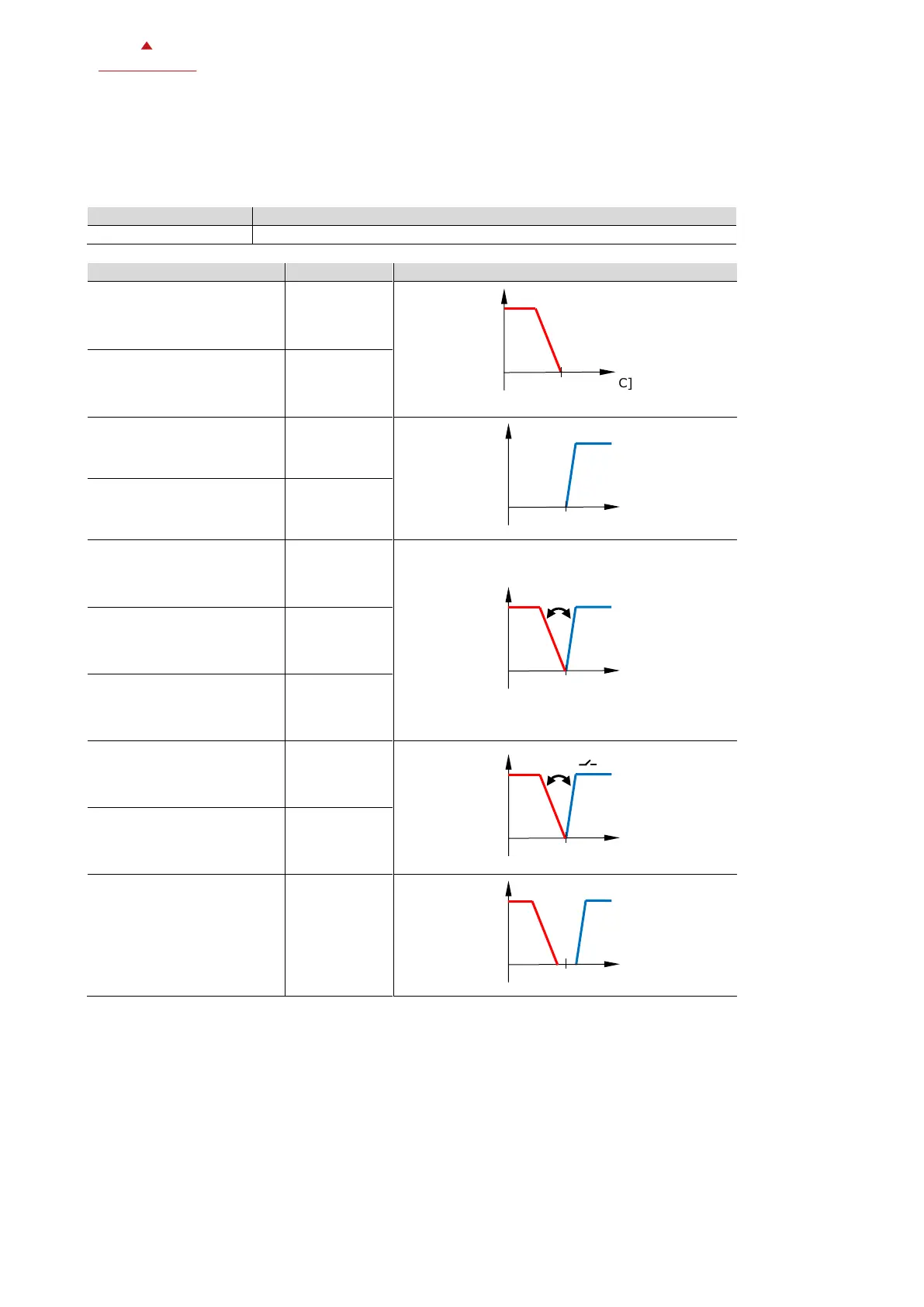
Valve control diagram (comfort mode)
2-pipe system
Heating only
2-pipe system
Cooling only
2-pipe system
manual heating or cooling
4-pipe system
manual heating or cooling
2-pipe system
auto heat/cool changeover
4-pipe system
auto heat/cool changeover
4-pipe system
Heating and cooling

 Loading...


