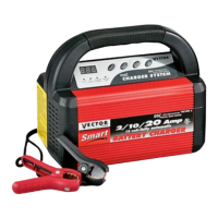
After the
clamps are connected, AC is connected. The charger
will show
a
circulating pattern
on the Digitc
Display. This
pattern indicates power is applied. Press the
ON/OFF button to prepare the
charger to chang
to an operating, mode. Press
the
2/10/20/35
A button and the
charger will begin charging
at 2 Amp:
Pressing the
2/10/20/35A switch again will advance the charge
rate to 10A, then 20A, then
35A.
Pressin
the switch
again will turn OFF the charger output and the
display will show the circulating
pattern,
see
Figure 4E
Note that
each time the charger rate is changed, the
charger sounds
a beep
tone. The
only time the select©
charge rate
does
not display at the full selected
rate is when the battery is nearly
full and charging at eithe
steps two or three. The display will
be
showing
a slowing charge rate. To return
to 2A, press the
2/10/20/35/
button. When the battery is fully
charged, the charging Complete
LED is lit and "FUL" is displayed
on th
Digital Display.
CONNECTING
IF BATTERY IS INSTALLED IN
A VEHICLE
a) Check polarity of battery
posts
-
For top-mounted battery
connectors, the Positive
post (marked POS, P,
-+
usually has
a
larger
diameter than the Negative
battery post (marked NEG,
N,
-).
For side-mounted batter
connectors, the
terminals are marked Positive
-red ana Negative -black.
b)
Attach charger
clamps to battery connections,
as
follows, ensuring
a good connection (if there is
a mistake
the Reverse Polarity
Indicator will light):
NEGATIVE-GROUNDED VEHICLE:
Connect the POSITIVE
(RED) charge
clamp
to the POSITIVE (POS, P,
+)
ungrounded
battery terminal.
Then, connect the NEGATIVE
(BLACK) charge
clamp to the vehicle
chassis, or the engine
block (away from the
battery). Do not connect the clamp
to tn
carburetor, fuel
lines, or sheet-metal
body parts: connect only to
a heavy
gauge
metal part
of the frame
c
engine
block. NOTE: NEGATIVE-GROUNDED
type systems
are the most common in today's
vehicles.
c)
Set
charger's charge rate to appropriate
setting
2/10/20/35A according to battery
size.
POSITIVE-GROUNDED
VEHICLE: Connect the
NEGATIVE (BLACK) charger
clamp to the
NEGATIVE (NEG
N,
-)
ungrounded battery post. Then,
connect the
POSITIVE (RED) battery clamp
to the vehicle chassis
or engin
part (away from
the battery). Do not connect
the clamp to the
carburetor, fuel lines,
or sheet-metal
body
part;
connect only
to a heavy gauge, stable metal
part of the frame or
engine block.
NOTE: If there is any problem
connecting the charger
clamps to the
battery terminals,
contact the Vectc
Technical Support
Department toll-free at
(866)
584-5504
for assistance.
d)
Plug
battery charger power cord into
grounded AC power
outlet and refer to
Appendix A at the
end of thi
document for approximate charging times.
e) When charging is completed, disconnect
cables and clamps
in reverse order
from which they
were connectec
NOTE:
Use
of Extension
Cords
If it is necessary to
use an extension cord,
as
is often
the case, observe
the following important
safety
information
•
Before using any extension
cord, ensure that the
wire size is at least
1 2 AWG for
up to 100 feet
and 10AWC
for longer than 100 feet.
•
Use
only
a good
quality,
good condition, UL-listed
extension cord,
and ALWAYS
connect charger
to the exter
sion cord before
plugging the extension cord
into
a
1
10/1 20 volt AC power
outlet. The
use of a poor
qua
ity extension
cord or one that is not in
good repair could
cause fire and/or
electric shock.
•
Use a
three-wire
extension cord with
a 3-prong plug and
3-conductor socket.
VEC09:
 Loading...