Replacing The Right Door (Ack Switch Panel Or Display) Before Turning Off Power
5
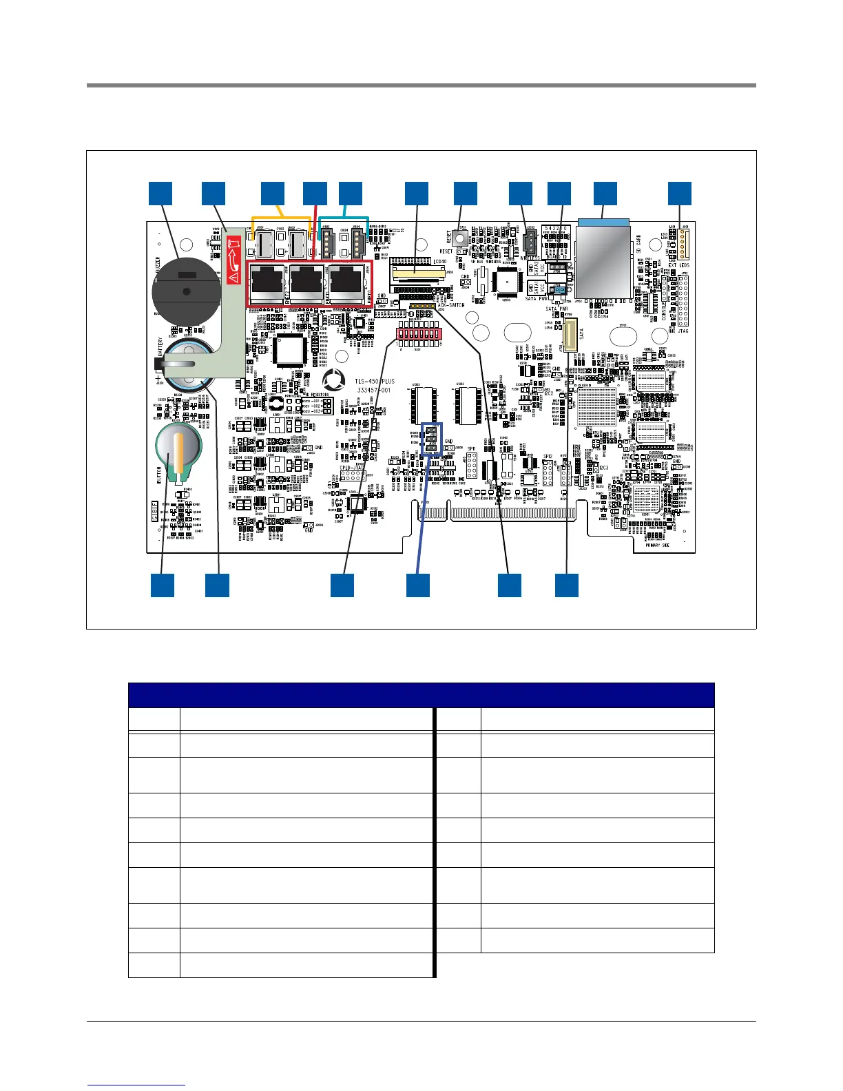
Figure 4. CPU board
Legend For Figure 4
Item Description Item Description
1 Console beeper 10 SD Card (in metal enclosure)
2 Battery isolator strip - to be removed prior to
startup
11 LED Backlight cable connector (optional dis-
play)
3 USB Type A connectors (2) 12 Features iButton
4 Ethernet (RJ-45) connectors (3) 13 Backup Battery
5 USB (0.1” pitch header) connectors (2) 14 Configuration DIP switches
6 Display cable connector (optional display) 15 SD card/SATA selection jumpers (J1201,
J1202 & J1203)
7 Reset button 16 Acknowledge Switch panel cable connector
8 USB module - wireless cable connector 17 SD/SATA board connector
9 SATA Type Jumpers (J1704 & J1708)
1
+
+
2 3 4 5 6 7 8 119 10
14 16 1712 13 15
TM