52
Pantallas de Diagnóstico (Diagnostic)
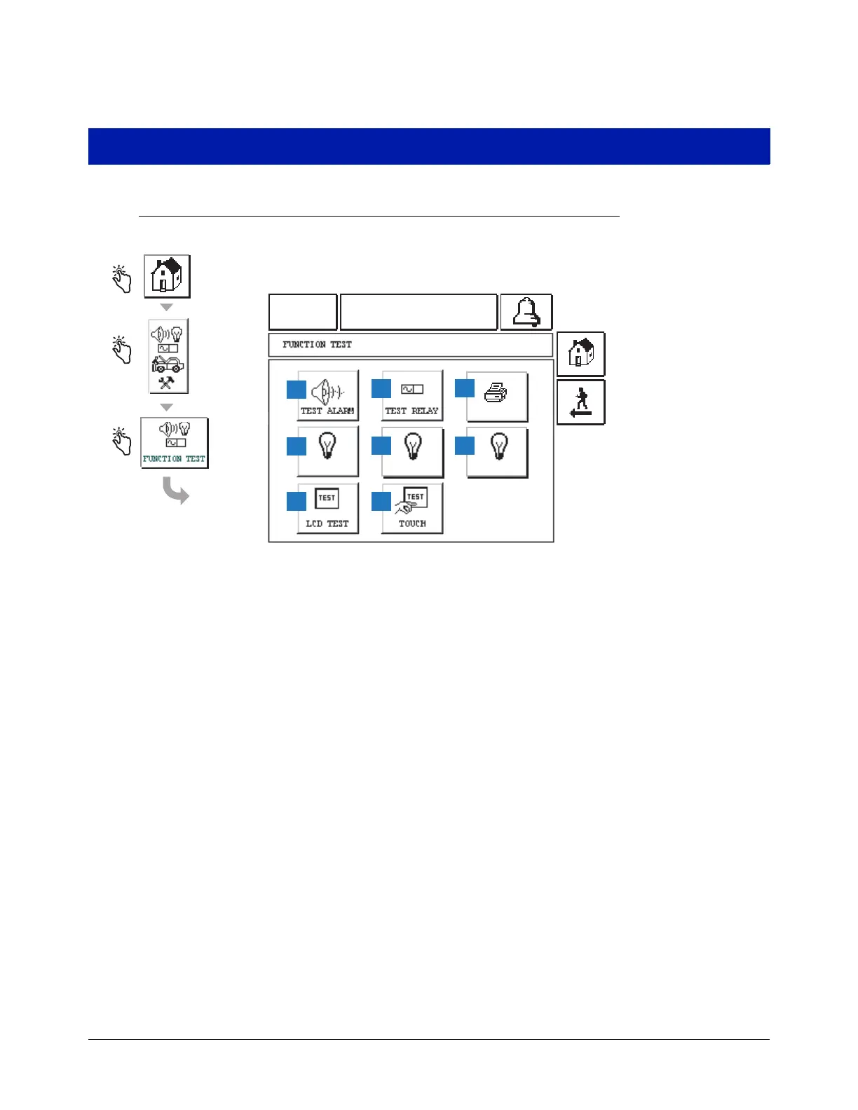
Pantalla de Menú de prueba de funciones (Function Test Menu)
Leyenda para cuadros numerados
01-01-2000
12:00 AM
ALL FUNCTIONS NORMAL
1
7
2
4
RED LED GREEN LED LCD OFF
5
8
3
6
Esta pantalla muestra las funciones de prueba del sistema.
1
Tecla ALARMA DE PRUEBA (TEST ALARM) -
púlsela y el zumbador de la consola se activará.
2
Te cla RE L É DE PRUEBA (TEST RELAY) - púlsela
y el relé se activará durante cinco segundos.
3
Tecla Impresora (Printer) - púlsela y una línea de
prueba se imprimirá en una impresora conectada.
4
Tecla LED ROJO (RED LED) - púlsela y el LED
rojo del panel delantero se encenderá durante
varios segundos.
5
Tecla LED VERDE (GREEN LED) - púlsela y el LED
verde del panel delantero se encenderá durante
varios segundos.
6
Tecla LCD APAGADA (LCD OFF) - púlsela y la luz
de fondo de la pantalla de Visualización (Display) se
apagará. Púlsela de nuevo para encender la luz de
fondo de la pantalla de visualización.
7
Tecla PRUEBA DE LCD (LCD TEST) - púlsela y se
mostrará un modelo de prueba de vídeo durante
varios segundos y luego desaparecerá.
8
Tecla PRUEBA TÁCTIL (TOUCH) - púlsela para
mostrar la pantalla de Prueba táctil LCD (LCD
Touch Test) (página 53).