18
5 Connecting to power supply
VEGAPULS C 11 • Two-wire 4 … 20 mA
58340-EN-200806
5 Connecting to power supply
5.1 Preparing the connection
Always keep in mind the following safety instructions:
•
Carryoutelectricalconnectionbytrained,qualiedpersonnel
authorised by the plant operator
Warning:
Only connect or disconnect in de-energized state.
Thedataforpowersupplyarespeciedinchapter"Technical data".
Note:
Power the instrument via an energy-limited circuit (power max. 100 W)
acc. to IEC 61010-1, e.g.
•
Class 2 power supply unit (acc. to UL1310)
•
SELV power supply unit (safety extra-low voltage) with suitable
internal or external limitation of the output current
Keepinmindthefollowingadditionalfactorsthatinuencetheoperat-
ing voltage:
•
Lower output voltage of the power supply unit under nominal load
(e.g. with a sensor current of 20.5 mA or 22 mA in case of fault)
•
Inuenceofadditionalinstrumentsinthecircuit(seeloadvaluesin
chapter " Technical data")
Thedeviceissuppliedwithaxedconnectedcable.Ifanextensionis
required, a standard two-wire cable can be used.
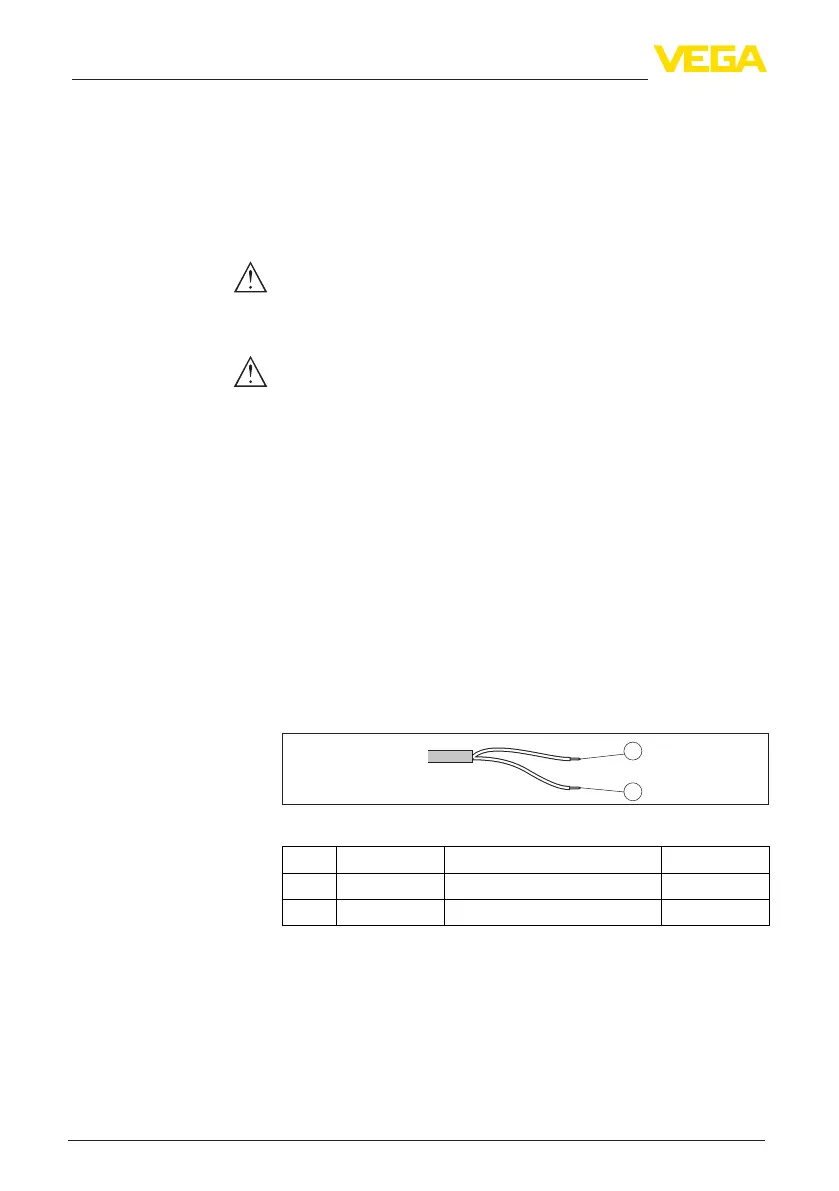
5.2 Wiring plan
1
2
Fig. 17: Wire assignment in permanently connected connection cable
Wire colour Function Polarity
1 Brown Voltage supply, signal output Plus (+)
2 Blue Voltage supply, signal output Minus (-)
5.3 Switch-on phase
After connection to the power supply, the device carries out a self-
test:
•
Internal check of the electronics
•
Output signal is set to failure
The current measured value is then output on the signal cable.
Safety instructions
Voltage supply
Connection cable
Wire assignment, con-
nection cable
 Loading...