44
13 Supplement
VEGAPULS C 11 • Two-wire 4 … 20 mA
58340-EN-200806
2
1
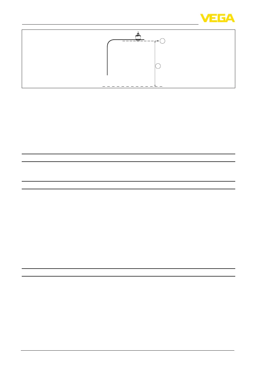
Fig. 23: Data of the input variable
1 Reference plane
2 Measuredvariable,max.measuringrange
Max. measuring range
5)
8 m (26.25 ft)
Recommended measuring range
6)
up to 5 m (16.4 ft)
blocking distance
7)
Ʋ Modes 1, 2, 4 0 mm (0 in)
Ʋ Mode 3 ≥250mm(9.843in)
Switch-on phase
Start-up time with operating voltage U
B
< 15 s
Starting current (for run-up time) ≤3.6mA
Output variable
Output signal
4 … 20 mA
Range of the output signal 3.8 … 20.5 mA (default setting)
Signal resolution 0.3 µA
Resolution, digital 1 mm (0.039 in)
Fault signal, current output (adjustable) ≤3.6mA,>=21mA,lastvalidmeasuredvalue
Max. output current 22 mA
Load See load resistance under Power supply
Starting current
≤3.6mA;≤10mAfor5msafterswitchingon
Damping (63 % of the input variable),
adjustable
0 … 999 s
Deviation (according to DIN EN 60770-1)
Process reference conditions according to DIN EN 61298-1
Ʋ Temperature +18 … +30 °C (+64 … +86 °F)
Ʋ Relative humidity 45 … 75 %
Ʋ Air pressure 860 … 1060 mbar/86 … 106 kPa (12.5 … 15.4 psig)
Installation reference conditions
Ʋ Distance to installations >200mm(7.874in)
5)
Depending on application and medium
6)
With bulk solids
7)
Depending on the operating conditions
 Loading...