Do you have a question about the Vega VEGASWING 61 and is the answer not in the manual?
Provides information for mounting, connection, setup, maintenance, and fault rectification.
Identifies the manual's intended audience as trained qualified personnel.
Explains symbols and their meanings used throughout the manual.
Specifies that operations must be performed by trained specialist personnel.
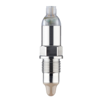
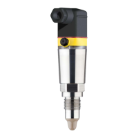
Defines the VEGASWING 61 as a level sensor and emphasizes correct usage.
Highlights hazards arising from inappropriate or incorrect instrument use.
Stresses observance of regulations, guidelines, and proper instrument condition.
Mandates observation of safety markings and tips directly on the device.
Confirms the device meets EC guideline requirements, indicated by the CE mark.
States compliance with functional safety standards IEC 61508 and IEC 61511.
Advises noting Ex-specific safety information for installation in hazardous areas.
Outlines the company's environmental management system and user obligations.
Details the components and scope of delivery for the VEGASWING 61.
Explains how the VEGASWING 61 functions as a level sensor using a tuning fork.
Describes how to check the switching condition and adapt the instrument.
Provides guidance on proper packaging, handling, and storage conditions.
Ensures suitability of instrument parts for process conditions and advises on installation position.
Details methods to protect the instrument from moisture penetration during installation.
Provides guidance on installing the instrument, including considerations for welded sockets.
Details the process and considerations for using welded sockets for installation.
Covers mounting in adhesive products, inflowing media, and with enamel coating.
Explains the function of the gas-tight leadthrough and caution for medium penetration.
Details safety instructions, voltage supply, and connection cable requirements.
Outlines the step-by-step process for connecting the instrument to power.
Illustrates wiring configurations for single chamber housing versions.
Shows wiring for the IP 66/IP 68, 1 bar version of the instrument.
Covers checking switching condition, signal lamp, and DIL switches for sensitivity.
Details the signal lamp and DIL switch for sensitivity adjustment on the electronics module.
Presents an overview of switching conditions based on mode and level.
Explains qualification for SIL2/SIL3 and WHG approval, and general test information.
Describes methods for carrying out recurring function tests according to WHG and SIL.
Details the test procedure, timing, and expected sensor/relay outputs.
Defines criteria for passing or failing the function test based on signal outputs.
States that no special maintenance is required for proper operation.
Covers failure causes, fault rectification, and service hotline contact.
Provides instructions for replacing a defective electronics module.
Outlines the procedure for sending the instrument in for repair.
Details steps for dismounting, including warnings about process conditions.
Provides information on the proper disposal and recycling of the instrument.
Lists detailed technical specifications including materials, dimensions, and performance.
Presents dimensional drawings for different housing versions and protection ratings.
Illustrates optional features like gas-tight leadthrough and temperature adapter.
Covers legal aspects of product protection, patents, and company trademarks.