Do you have a question about the Vega VEGAVIB 61 and is the answer not in the manual?
Provides information for mounting, connection, setup, maintenance, and fault rectification.
Manual is directed to trained specialist personnel.
Explains symbols used in the manual (information, caution, warning, danger, Ex, SIL, list, action, sequence, battery disposal).
Operations must be carried out by trained specialist personnel.
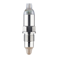
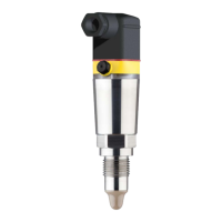
VEGAVIB 61 is a sensor for point level detection; proper use ensures operational reliability.
Inappropriate use can lead to application-specific hazards like vessel overfill.
Instrument must be operated in a technically flawless condition; user must observe regulations.
Safety approval markings and safety tips on the device must be observed.
Device fulfills EU guidelines; CE marking confirms testing.
VEGAVIB 61 meets functional safety requirements according to IEC 61508.
Notes Ex-specific safety information for installation and operation in Ex areas.
Information on environmental protection and management system.
Lists scope of delivery and constituent parts of VEGAVIB 61.
VEGAVIB 61 is a point level sensor with vibrating rod for level detection.
Details factory settings and adaptation for lower density products.
Describes packaging for transport and adherence to ISO 4180.
Covers suitability for process conditions, switching point, moisture, transport, pressure/vacuum, handling.
Protrusion into vessel, avoiding filling stream, horizontal installation, protective sheets.
Impact of material cones, installation location, distance from wall.
Precise switching point with horizontal installation, or inclined mounting.
Avoid mounting in filling stream to prevent false signals.
Protects vibrating element in applications like grit chambers.
Safety instructions, voltage supply, connection cable, Ex applications.
Step-by-step guide for connecting wires to terminals.
Illustrates wiring for single chamber housing, applicable to non-Ex and Ex-d.
Wiring plan and wire assignment for IP 66/IP 68 (1 bar) version.
Identifies display and adjustment elements on the electronics module.
Details potentiometer, DIL switch, and signal lamp.
Overview of switching conditions based on mode and level.
Qualification for SIL2/SIL3, instrument combinations, and detailed test procedures.
No special maintenance required if used properly.
Operator responsibility for faults, causes, rectification, and service hotline.
Table with errors, reasons, and rectifications for signal issues.
Procedure for interchanging electronics modules.
Procedure for returning instrument for repair, including forms and packaging.
Warning about process conditions and reverse order of mounting steps.
Information on recycling materials and WEEE directive.
General data, materials, process fittings, weight, lateral load, torque.
Dimensional drawings for various housing versions and thread types.
Information on global protection of VEGA product lines.
States that brands and names are property of their lawful proprietors.