Do you have a question about the Vega VEGATOR 141 and is the answer not in the manual?
Provides an overview of the manual's purpose and scope for device operation and maintenance.
Identifies trained and qualified personnel as the intended audience for this manual.
Explains the various symbols employed in the manual for clear communication and safety.
Specifies that only trained, qualified personnel should operate and work on the device.
Defines the intended application of the VEGATOR 141 and conditions for operational reliability.
Highlights potential hazards and damage resulting from improper or incorrect use of the product.
Outlines general safety regulations, directives, and user responsibilities for safe operation.
Provides specific installation and operation information applicable only to the USA and Canada.
Details safety requirements for operating the device in explosion-proof (Ex) areas.
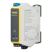
Lists the components included in the scope of delivery for the VEGATOR 141.
Explains the fundamental working mechanism of the VEGATOR 141 for level detection.
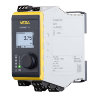
Describes the location and types of adjustment elements for configuring the device.
Provides guidelines for handling, transporting, and storing the instrument to prevent damage.
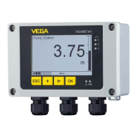
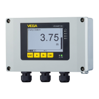
Details general mounting requirements, options, and ambient condition considerations for installation.
Covers essential safety instructions and considerations before making electrical connections.
Explains the selection between active and passive input modes for sensor data.
Provides a step-by-step guide for making the electrical connections to the instrument.
Illustrates the electrical connections for various input and output configurations.
Demonstrates a specific wiring example for controlling multiple controllers with one sensor.
Overview of the physical components used for device adjustment and configuration.
Details control lamps, DIL switches, and potentiometers for setting operating mode, delays, and switching points.
Guides on setting the switching point for continuous 4-20mA sensor inputs.
Explains how to adjust the switching point for capacitive limit level sensors.
Describes the procedure for testing the correct functioning of the instrument after setup.
Presents a diagram illustrating switching statuses based on level and operating mode.
Provides information on routine maintenance requirements for the device during normal operation.
Outlines the operator's responsibility and initial steps for troubleshooting malfunctions.
Explains how the controller monitors for faults and triggers fault signals.
Details the steps for returning the instrument for repair, including form completion and packaging.
Instructs on how to safely remove the instrument by reversing installation steps.
Provides guidance on the environmentally responsible disposal of the instrument.
Information on available or pending approval versions for use in hazardous locations.
Confirms the device's compliance with applicable EU directives, indicated by CE marking.
Details the instrument's compliance with functional safety requirements as per IEC 61508.
Highlights the company's commitment to environmental protection through its certified management system.
Provides detailed specifications for the device, including electrical, environmental, and mechanical properties.
Presents the physical dimensions and mounting details of the VEGATOR 141.
States that VEGA product lines are protected by industrial property rights globally.
Confirms that all brands and names used are the property of their respective owners.
| Brand | Vega |
|---|---|
| Model | VEGATOR 141 |
| Category | Controller |
| Language | English |