14
6 Setup
VEGATOR 141 •
46838-EN-210714
6 Setup
6.1 Adjustment system
1
2
3
4
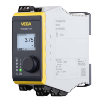
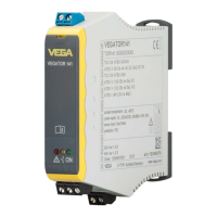
Fig. 3: Display and adjustment elements
1 Potentiometer for switching point adjustment
2 DIL switch block
3 Signal lamps (LEDs)
4 Hinged front cover
6.2 Adjustment elements
Control lamps (LED) in the front plate indicate operation, switching
status and fault signal.
•
Green
– Operating control lamp
– Mains voltage on, instrument is operating
•
Red
– Fault indicator
– Fault on the sensor circuit due to sensor failure or line break
– The relay deenergises in case of failure
Control lamps
 Loading...