Do you have a question about the Veikong VFD500M Series and is the answer not in the manual?
Company information, product series overview, and contact details.
General precautions and warnings for safe operation and handling of the inverter.
Specific safety guidelines categorized by installation, wiring, and operation stages.
Precautions regarding contactor use, lightning protection, altitude, power input, and disposal.
Details on product naming conventions, series instructions, and model specifications.
Comprehensive technical data including input/output, control modes, and environmental requirements.
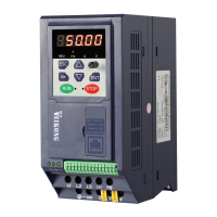
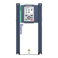
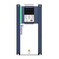
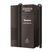
Physical appearance, dimensions, and mounting hole details of the inverter.
Standard wiring diagrams for main and control circuits.
Description and function of main circuit terminals.
Cable specifications, screw tightening, and important wiring safety guidelines.
Schematic diagrams and functional descriptions of control circuit terminals.
Explanation of LED indicators, keys, and their functions on the operating panel.
Details on keyboard operation modes and digital tube display formats.
Parameters related to inverter starting, stopping, and braking.
Configuration for acceleration and deceleration curve settings.
Settings for analog and pulse signal inputs.
Configuration for analog and pulse signal outputs.
Settings for various digital input functions.
Configuration of multi-function digital output terminals.
Parameters for setting digital outputs, including frequency detection.
Parameters for Motor 1, including type, rating, and auto-tuning features.
Settings for Volts/Frequency (V/f) control of Motor 1.
Parameters for vector control of Motor 1.
Configuration settings for torque control.
Parameters related to energy saving features.
Configuration for creating custom function code menus.
Settings for keypad functions, display options, and monitoring.
Parameters for carrier frequency, PWM modes, and drive configuration.
Configuration of various drive protection functions like overvoltage and undervoltage.
Settings for motor overload and other protection features.
Parameters for tracking current fault types and status.
Parameters for recording historical fault data.
Parameters for monitoring inverter status, running modes, and frequencies.
Configuration settings for Modbus communication.
Parameters for configuring the Proportional-Integral-Derivative (PID) control loop.
Settings for sleep mode and wake-up conditions based on frequency or pressure.
Configuration parameters for the built-in Simple PLC functionality.
Settings for delay units used in logic and output functions.
Parameters for variable selectors and logic blocks for flexible control.
Configuration settings for multi-functional counters.
Basic configuration parameters specific to Motor 2.
List of faults, possible causes, and recommended solutions for inverter issues.
Information on inverter warning codes, reasons, and measures to take.
Guidelines and check items for routine daily maintenance of the inverter.
Items for regular inspection and information on wearing parts replacement.
Details on warranty coverage, terms, and conditions.
Overview of Modbus RTU protocol format and message structure.
Detailed descriptions of Modbus command codes for reading and writing data.
Information on diagnostic functions and handling of abnormal responses.
Explanation of register data types, CRC checks, and address distribution.
Instructions on how the inverter operates as a Modbus master station.
| Model Series | VFD500M Series |
|---|---|
| Category | Inverter |
| Cooling Method | Forced air cooling |
| Enclosure Rating | IP20 |
| Control Method | V/F control |
| Output Frequency Range | 0-600Hz |
| Overload Capacity | 150% rated current for 60 seconds |
| Braking | Built-in braking unit |
| Communication Interfaces | RS485 |
| Protection Features | Overcurrent, Overvoltage, Undervoltage, Overheat, Overload, Short Circuit |
| Operating Temperature | -10°C~+40°C (Derating if exceeding 40℃) |
| Storage Temperature | -20°C to +60°C |