Do you have a question about the Veikong VFD530 and is the answer not in the manual?
Details safety precautions categorized by use stage (Before Installation, During Installation, Wiring, Before Power-on).
Discusses specific precautions like contactor usage and lightning protection.
Explains how to interpret the model designation on the nameplate.
Provides a table and explanation of VFD530 inverter models and their technical data.
Details technical specifications such as input voltage, frequency, and overload capacity.
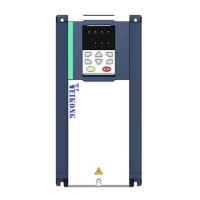
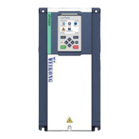
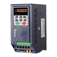
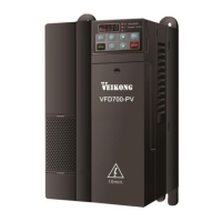
Illustrates the physical appearance and components of the VFD530 drive.
Provides dimensions and mounting hole details for the VFD530 keypad and its holder.
Details the steps for removing and installing the cover and inlet plate for different sizes.
Provides the standard wiring diagram for control and main circuits.
Shows diagrams of main circuit terminals for different sizes (A-C, D, E, F-G).
Provides a table detailing main circuit cable and screw specifications.
Lists important cautions for power supply, DC, and motor wiring.
Shows the layout and labels of the VFD530 control circuit terminals.
Discusses electromagnetic compatibility (EMC) issues and provides solutions.
Explains the components of the operating panel and the function of each key.
Describes the four-layer display hierarchy and menu navigation modes.
Explains the display of decimal and binary data on the digital tubes.
Provides a procedure for commissioning the inverter for the first time.
Details basic functions like user password, access authority, and parameter copy/backup.
Covers parameters related to main and auxiliary frequency source selection and gains.
Details parameters for starting modes, startup frequency, and DC braking.
Covers parameters for acceleration/deceleration curve selection and time settings.
Details parameters for analog and pulse input settings, including curve configurations.
Covers parameters for HDO and AO output settings, including function signal selection and offsets.
Details parameters for multi-function digital inputs (DI), including their functions and settings.
Details parameters for multi-function digital outputs (DO) and relay outputs.
Covers parameters related to encoder type, line number, and pulse direction.
Details motor parameters such as type, rated power, voltage, current, frequency, and RPM.
Covers parameters for VF curve settings, including linear, multi-point, and separation types.
Details parameters for motor 1 vector control, including PI parameters and torque limits.
Covers parameters for torque control, including input source, digital setting, and acceleration/deceleration times.
Details parameters for energy saving control, including electricity meter count and power factor.
Covers parameters for synchronous motor control, including initial position identification and MTPA control.
Allows users to define custom function code menus for quick access.
Details parameters for keypad functions, monitoring displays, and personalized settings.
Covers carrier frequency settings, PWM modulation methods, and energy braking.
Details drive protection functions like overvoltage stall, undervoltage stall, and over-speed detection.
Covers motor overload and overheating protection parameters, including settings and curves.
Details parameters for tracking current, output frequency, bus voltage, and input/output terminal status at fault.
Lists parameters for monitoring running frequency, set frequency, bus voltage, output current, and drive status.
Covers Modbus communication settings like type, address, baud rate, and data format.
Details CANopen communication parameters, including address, baud rate, and working status.
Covers PID control parameters, including reference source, digital settings, and feedback sources.
Details parameters for sleep mode and wake-up selection based on frequency or analog input.
Covers parameters for the Simple PLC function, including running mode and step times.
Details parameters for delay units used in programming logic.
Covers parameters for variable selectors and logic blocks, used for flexible logic functions.
Details parameters for multi-functional counters, including input value, set value, and electronic gears.
Covers parameters for PID control, including reference source, feedback, and output characteristics.
Details basic parameters for Motor 2, referencing Motor 1 settings.
Lists fault names, codes, possible causes, and solutions for inverter faults.
Describes warning types, their reasons, and recommended measures.
Guides the selection of braking resistors and units based on application and power.
Lists optional PG cards and supported encoders for the VFD530.
Describes the MT500-IOEX1 expansion card for adding DI, AI, and DO channels.
Introduces the MT500-CAN1 communication card for CANopen network connectivity.
Provides daily checks for ensuring proper inverter operation and longevity.
Lists vulnerable parts like fans and capacitors and their replacement times.
Outlines the warranty terms and conditions for the frequency inverter.
Describes the RS485 communication protocol and default data format.
Explains the structure of Modbus RTU messages, including start, address, PDU, and CRC.
Details Modbus command codes for reading, writing, and diagnostic functions.
Explains how register addresses are distributed and how to calculate them for EEPROM saving.
Describes how the VFD530 can function as a Modbus master station.
Provides wiring guidance for the control circuit, noting brake feedback and fault/brake control signals.
Explains the process of motor self-learning and encoder self-learning.
Covers lifting adjustment, including start-stop logic and parameters for open-loop hoisting.
Explains brake feedback connection and parameter settings (P51.17).
Lists special lifting function parameters, including frequency and current settings for brake release/application.