In order to prevent the device inlet water temperature exceed 55°C,
"thermostatic mixture valve" should be used as easily supplied from the
market at solar power system outlet or the device inlet.
Fault Codes
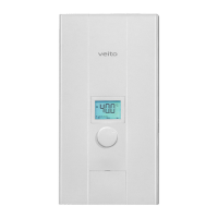
In certain situations, device gives a fault code (from E01 to E06) on the
LCD screen as indicated on the image on the right (BLUE S) or flashes
failure LEDs located on the electronic card in a certain combination (BLUE)
and stops its operation. This situation indicates that the device stops
heating due to failure. Please try to eliminate the failure according to
instructions given in the “Problem Detection and Service” section in the
guide. Therefore, you shall get rid of unnecessary service costs. When the
failure status is eliminated, the failure code on the LCD screen shall be
automatically deleted (BLUE S) or failure LEDs on the electronic card shall
automatically dim-off (BLUE) and device continues heating.
Cleaning and Maintenance
Do not use strong abrasives or melter liquids during the device cleaning.
These substances may damage to plastic connections. Device may be
cleaned with warm water by using a soft fabric. Prior to cleaning the device,
fuse should be shut-off and electricity should be interrupted. This prevents
accidental operation of the device during cleaning. Contamination rate and
contained lime amount of the water being used determines the cleaning
period. For instance, cleaning should be performed at least once a week if
used daily in the water with high contamination rate. Device, electricity and
water installations should be controlled by an authorized technician in
minimum two years period.
Cleaning the Inlet Water Filter (I) and Removing the Flow Limiter (II)
Inlet water filter is located within the device water inlet and controlled and
cleaned regularly, not only when prevents operation of the device after
blocking or replaced with the new one. Interrupt the inlet water for cleaning
operation. Remove the device front cover and open the stopper located on
the water inlet component by rotating at removal direction. Now, you can
access the inlet water filter (I) and flow limiter (II) located in the slot.