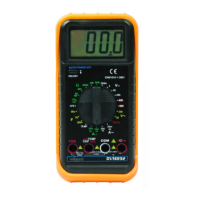
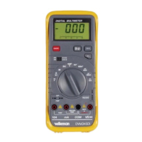
DVM851
V. 03 – 23/10/2015 11 ©Velleman nv
9.6 TRANSISTOR hFE TEST (0-1000)
Do not conduct transistor measurements on live circuits.
For transistor test use the included adaptor socket.
Voltage Measurement
10.1 DC VOLTAGE MEASUREMENT
Do not measure circuits that may contain voltages > 600V
Use extreme caution when measuring voltages higher than
60Vdc or 30Vac rms.
Always place your fingers behind the protective edges of the
test probes while measuring!
1. Connect the red test lead to the "VmA" jack and the black lead to
the "COM" jack.
2. Set the rotary switch in the desired DCV position. If the voltage to
be measured is unknown beforehand, you should set the range
switch in the highest range position and then reduce gradually
until the ideal resolution is obtained.
3. Connect the test leads to the source being measured.
4. Read the voltage value on the LCD display along with the polarity
of the red lead connection.
10.2 DC CURRENT MEASUREMENT
Do not measure current in circuits with voltages > 600V
Use extreme caution when measuring voltages higher than
60Vdc or 30Vac rms.
Always place your fingers behind the protective edges of the
test probes while measuring!
1. Connect the red test lead to the "VmA" jack and the black test
lead to the "COM" jack (switch the red lead to the "10A" jack for
measurements between 200mA and 10A).
2. Set the rotary switch (DCA) in the desired position.
3. Open the circuit in which the current is to be measured and
connect the test leads to the circuit IN SERIES.
 Loading...