•
For Y
our
Records:
Serial Numb
er
____________
_
Date
of
Purchase _
___
_______
_
Name of Store
__
_____
___
__
_
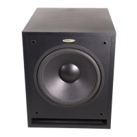
OWNER'S MANUAL
VELODYNE ULD-15 AND ULD-18
SERIES
II
SUBWOOFER SYSTEMS
Co
ngratulations
on
your purchase of a Velodyne ULD
Se
ri
es II Subwooler System. This system represents the
state of the art in accura
te
bass reproduction. Read and follow the instructions below to insu
re
safe and proper
syst
em
operation. Regardless
of
wh
ich installati
on
co
nf
iguration
yo
u choose, please carefully read the entire
BASIC INSTALLATION section of this manual. Save this manu
al
for future referenc
e.
Wa
rning
:
To
prevent fire or shock hazard, do not expose this equipment to rai n or moisture. To
avoid electrical shock do not open speaker enclosure or amp chassis cover. Please observe all
warnings
on
the equipment
it
self. There are no user serviceable parts inside. Please refer all
service question s to your authorized
Ve
lodyne dealer.
Ca
ution
: Risk
of
hazardou
s e
nergy
. Your ULD Subwoofer System has a very powerful ampli-
fier. Exercise extreme caution.
Do
not a
tt
empt a
ny
connection or disconnecti
on
with power
on
.
In
spect sp
ea
ker lead
co
nnections at
co
ntroller a
nd
woofer terminal plat
e.
Loose strands or frayed
wire
ca
n cau
se
a dangerous short circuit. Keep con nections
ou
t of reach of children.
Prior
To Insta
llation
: Your ULD Subwoofer Syst
em
incl
ud
es the
fo
llowing Ihree separate components:
1
~
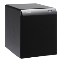
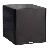
A cabinet incorporating the bass driver, servo interface jack, and speaker terminals. Observe
th
e
above caution notice.
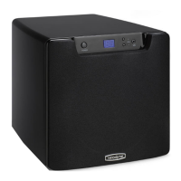
2) A servo
controller
wh
ich includes the High Gain Servo
co
rr
ection circuitry. a 400 watt RMS
amplifier. high and low pass crossovers, input and
ou
tput jacks, level control. servo
in
terface jack.
and speaker terminal
s.
Observe the above caution notice.
3)
Cable kit with 25' phono cable for connection from controller to woofer cabinet, and a 3' pat
ch
cord for connecting the controller to your pre-amp. Speaker wire is not included.
Please unpack the system carefull
y.
saving t
he
carton and all packaging materials for future u
se
. Remove all
staples used to seal the carton as they can scratch the cabinet.
BASIC INSTALLATION
(Refer to Figure
1)
System Conn
ec
tion : The servo controller is designed to be installed between your pre-amplifier and amplifier
(or between the amp and pre-amp sections of a receiver or integrated amp). Make all connections with the servo
controller unplugged.
1)
Install the includ
ed
3'
patch cord between your pre-amp's output jacks and the servo
co
ntroller
(use FROM PRE AMP jacks).
2) Install a second patch cord between the servo controller (use TO POWER AMP jac
ks
) and your
amplifier's input
Jacks.
- 1-
 Loading...