12 VELUX
®
J1
65432132132121
132
+–
2132132132541
LINK FACU
BATTERY
DET.21DET.21
NL
NL
PENL
230V
230V
ERROR-MOTOR 1
ERROR-MOTOR 2
ERROR-SMOKE DET.
ERROR-BREAK GLASS
RAIN SENSOR INPUT
ALARM ACTIVE
ERROR-TEMP. FUSE
MAINTENANCE
BATTERY
PSU2 OK
PSU1 OK
OPERATION
RESET
SETUP
RESET
73˚ C
TEMP. FUSE
TIME
AUTO CLOSE
TIME
OPENNIG
COMFORT
FRONT PANEL
BREAK GLASS POINTRAINRAIN IN COMFORTSMOKERAIN OUT ERRORALARM
FUSE: 25A
MOTOR 2MOTOR 1230V/50Hz
+–
24V
24V
1
ON
23456
654321
678954321
J1
J1
9
a
b
Up to 10 break-glass points can be connected
to each control system.
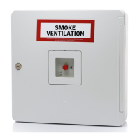
Installation
Break-glass points KFK 100/101/102/103/104
are surface mounted and should be connected in
accordance with current national legislation. The
installation surface must be smooth and level.
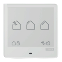
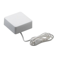
Connection
The break-glass point is connected to the
control unit by means of a 6-core cable with a
minimum cross-section of 0.5 mm
2
. This cable
can be up to 100 m long.
Break-glass points KFK 100/101/102/103/104
must be installed in continuous single line con-
nections to ensure that the complete line from
the control unit to the last break-glass point
is monitored. Individual connection to more
than one break-glass point does not allow for
monitoring.
The first additional break-glass point must be
connected to the terminals in the control unit.
When connecting, lead cable through the rub-
ber membrane and fasten with cable tie.
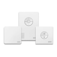
Terminal module J1 (jumper)
Terminal module J1 in the control unit must be
moved to the last or only break-glass point – ie
to the break-glass point placed farthest away
from the control unit
a
.
Note: If no break-glass points are in the
system, the terminal module in the control unit
must be moved from the middle and lowest pin
to the top and middle pin
b
.
Colour of frame for break-glass point in
control unit
The white frame can be replaced by the
coloured frame supplied (applies to KFX 211,
212, 213 and 214 and KFC 210 and 220). See
page 32.
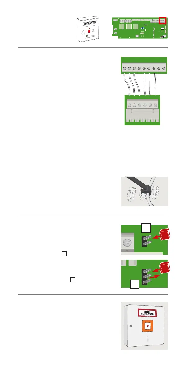
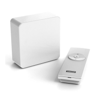
Break-glass point
KFK 100