16 VELUX
®
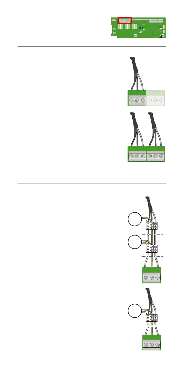
J1
65432132132121
132
+–
2132132132541
LINK FACU
BATTERY
DET.21DET.21
NL
NL
PENL
230V
230V
ERROR-MOTOR 1
ERROR-MOTOR 2
ERROR-SMOKE DET.
ERROR-BREAK GLASS
RAIN SENSOR INPUT
ALARM ACTIVE
ERROR-TEMP. FUSE
MAINTENANCE
BATTERY
PSU2 OK
PSU1 OK
OPERATION
RESET
SETUP
RESET
73˚ C
TEMP. FUSE
TIME
AUTO CLOSE
TIME
OPENNIG
COMFORT
FRONT PANEL
BREAK GLASS POINTRAINRAIN IN COMFORTSMOKERAIN OUT ERRORALARM
FUSE: 25A
MOTOR 2MOTOR 1230V/50Hz
+–
24V
24V
1
ON
23456
DET.21
MOTOR 1
M
DET.21
MOTOR 1
M
M
DET.21DET.21
MOTOR 2MOTOR 1
ET
1
M
T
R
DET.21DET.21
MOTOR 2MOTOR 1
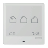
Each terminal is intended for 24 V DC and max 10 A.
Control unit KFC 210 (10 A)
In this example, only motor terminal 1 is active.
Max 4 smoke ventilation windows
GGL/GGU -K-- ----40
or
1 smoke ventilation window CSP can be con-
nected to the control unit.
Control unit KFC 220 (2 x 10 A)
In this example, both motor terminals 1 and 2 are
active.
Max 8 smoke ventilation windows
GGL/GGU -K-- ----40 (max 4 windows per motor
terminal)
or
2 smoke ventilation windows CSP can be con-
nected to the control unit.
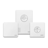
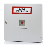
Terminal module
To ensure cable monitoring, the terminal module
in the control unit must be moved to the last con-
nection between smoke ventilation windows
GGL/GGU -K-- ----40 or CSP and the cables from
the control unit.
Note: In case motors operate in the wrong direc-
tion, transpose the 2 motor cables in the terminal.
Motor terminals