VELUX
®
17
J1
65432132132121
132
+–
2132132132541
LINK FACU
BATTERY
DET.21DET.21
NL
NL
PENL
230V
230V
ERROR-MOTOR 1
ERROR-MOTOR 2
ERROR-SMOKE DET.
ERROR-BREAK GLASS
RAIN SENSOR INPUT
ALARM ACTIVE
ERROR-TEMP. FUSE
MAINTENANCE
BATTERY
PSU2 OK
PSU1 OK
OPERATION
RESET
SETUP
RESET
73˚ C
TEMP. FUSE
TIME
AUTO CLOSE
TIME
OPENNIG
COMFORT
FRONT PANEL
BREAK GLASS POINTRAINRAIN IN COMFORTSMOKERAIN OUT ERRORALARM
FUSE: 25A
MOTOR 2MOTOR 1230V/50Hz
+–
24V
24V
1
ON
23456
CSP
Electrical cables should be drawn according to regulations by qualified per-
sonnel. The control system and its cables should be installed in compliance
with current national legislation and the requirements of local authorities.
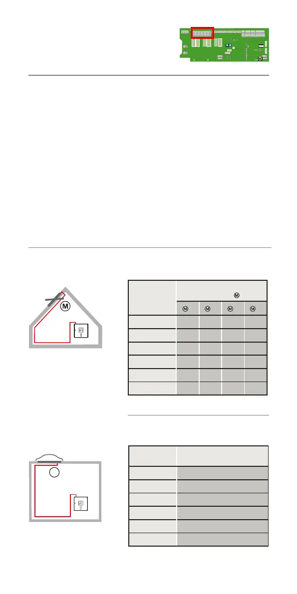
Maximum cable length/prescribed cross-sectional size of
cables
The maximum allowed cable lengths between control unit and motor and the
prescribed cross sectional sizes of the cables are given in the table below. The
cable must be protected according to National/European Standards.
Calculation of max. cable length: 56 x A/l
A is cable cross-section and I is max motor current in total.
Allowed maximum voltage drop in the cable: 2 V
Operation current: The total of all motor currents.
Cable cross-section per motor terminal for smoke ventilation window
GGL/GGU -K-- ----40
Cable cross-section per motor terminal for smoke ventilation window CSP
Wiring
Cable cross-
section
Max. cable length for
number of motors
*)
1
2
3
4
3 x 1.5 mm
2
33 m 16 m 11 m 8 m
*) 5 x 1.5 mm
2
67 m 33 m 22 m 16 m
3 x 2.5 mm
2
56 m 28 m 18 m 14 m
*) 5 x 2.5 mm
2
112 m 56 m 37 m 28 m
3 x 4 mm
2
89 m 44 m 29 m 22 m
3 x 6 mm
2
134 m 67 m 44 m 33 m
Cable cross-
section
Max. cable length *)
3 x 1.5 mm
2
8 m
*) 5 x 1.5 mm
2
17 m
3 x 2.5 mm
2
14 m
*) 5 x 2.5 mm
2
28 m
3 x 4 mm
2
22 m
3 x 6 mm
2
33 m
*) 2x2 conductors in parallel
Only one smoke ventilation window CSP per motor
terminal
*) 2x2 conductors in parallel
 Loading...