VELUX
®
25
J1
65432132132121
132
+–
2132132132541
LINK FACU
BATTERY
DET.21DET.21
NL
NL
PENL
230V
230V
ERROR-MOTOR 1
ERROR-MOTOR 2
ERROR-SMOKE DET.
ERROR-BREAK GLASS
RAIN SENSOR INPUT
ALARM ACTIVE
ERROR-TEMP. FUSE
MAINTENANCE
BATTERY
PSU2 OK
PSU1 OK
OPERATION
RESET
SETUP
RESET
73˚ C
TEMP. FUSE
TIME
AUTO CLOSE
TIME
OPENNIG
COMFORT
FRONT PANEL
BREAK GLASS POINTRAINRAIN IN COMFORTSMOKERAIN OUT ERRORALARM
FUSE: 25A
MOTOR 2MOTOR 1230V/50Hz
+–
24V
24V
1
ON
23456
ERROR - BREAK-GLASS POINT
The printed circuit board monitors for defects in the cable to any break-
glass points that are connected.
If the cable to the connected break-glass point(s) is interrupted, the yel-
low light-emitting diode flashes on and off. If the cable is short-circuited,
the yellow light-emitting diode is on permanently.
The error is also indicated in the integrated break-glass point and pos-
sible additional break-glass points.
Note: If no break-glass points are in the system, the terminal module in
the control unit must be moved from the middle and lowest pin to the
top and middle pin (see page 12).
ERROR - TEMP. FUSE
The printed circuit board monitors the temperature in the control unit.
If the temperature in the control unit rises above 70 ˚C, the temperature
fuse on the printed circuit board is activated and all connected windows
open for smoke ventilation. The yellow light-emitting diode is on perma-
nently until the printed circuit board has been replaced. After replac-
ing the printed circuit board, the installation must be service tested
thoroughly to ensure that the system works correctly.
The error is also indicated in the integrated break-glass point and pos-
sible additional break-glass points.
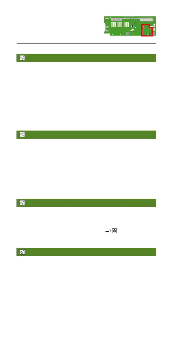
ALARM - ACTIVE
The red light-emitting diode on the front of the control unit is on per-
manently when the smoke ventilation function has been activated (from
break-glass point, smoke detector or external fire alarm).
The alarm can be reset by pressing the button
at the right. After
this, the light-emitting diode on the printed circuit board and in all break-
glass points are turned off.
ERROR - COMFORT VENTILATION
After an alarm or a power failure, it will take at least 2 minutes before
the comfort ventilation can be activated again.
Status and error indication
in control system
 Loading...